In part 2 of this three-part series, the author will discuss how hose tubing and routing can simplify maintenance and reduce hose failure. Read part one here.
By Mike P. Beining, Product Manager, Eaton

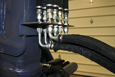
High-pressure hose must be routed to flex in only one plane.
To correctly route and properly install fluid conveying components during a machine prototyping, follow these 10 general rules. These guidelines are most useful during machine prototyping. Normal production procedures should be followed after all “bugs” have been removed.
- Start with large lines — Install the largest ID lines first as they are the hardest to bend and maneuver, especially in tight spaces. Then, the toughest part of the job is done. Smaller lines provide more routing versatility and can be more easily worked in tight spaces, so route each line to conserve maximum space. This not only results in a neater-looking installation, but makes future modifications or additions of accessories easier, more convenient and more economical.
- Correct hose length — The appearance and efficient operation of a system often depends on using proper length hoses. Excessive hose footage increases pressure drops and system cost. Hose assemblies are commonly manufactured to specified lengths as well as increments of lengths to minimize the size of the inventory, which must be carried. When computing hose length, remember that hose can elongate as much as 2% or contract as much as 4%.
- Hose flexing — A hose assembly is designed to flex or bend, not twist. In fact, if a large-diameter, high-pressure hose is twisted 7°, its service life can be significantly reduced, in some cases by as much as 90%. High- pressure hose must be routed to flex in only one plane. If plumbing requires that hose be routed through a compound bend, the hose should be “broken” into two or more sections so each will flex through only one plane. A spring guard will keep hose from bending beyond the minimum bend radius at the fitting, but it will not prevent the hose from twisting.
-

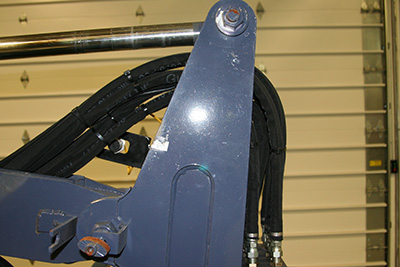
To achieve proper hose flexing, the hose should be positioned to bend like a hinge.
Pivot points — When hose must flex, route it through the pivot point around which the component is moving. This will result in the best and most efficient flexing of the hose line, use the least amount of hose and keep the hose within the contour of the machine. To achieve this, the hose should be positioned to bend like a hinge. Otherwise, the hose may have a tendency to take an S-bend, which is most likely to happen when the hose is pushed rather than bent. An S-bend installation results in excessive hose movement and reduced service life. When piping a flexible line through a pivot point, consider the relative positioning of the two end fittings to avoid an S-bend by following this procedure: Swing the moving component to its farthest point where the hose will experience its widest bend. If the fittings are placed in parallel planes at this point, the hose will tend to flex in a hinge-like manner when the component is swung back to the opposite end of its travel.
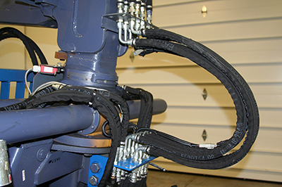
- Reciprocating motion — In addition to flexing, the ends of the hose may have to reciprocate. There are several design methods to do this:
- Hose reels — For use with high-pressure hydraulic hose, these reels are equipped with high-pressure swivel joints and a spring return to help rewind the hose.
- Festooning — Hose is hung in loops from a steel cable. As one point of the loop moves away from the other, the loops open to form an almost straight line.
- Rolling — Hose is arranged in an unbalanced U-shape with hinged tracks carrying the hose. One leg is left stationary and longer than the second, which is free to reciprocate parallel to the first.
-

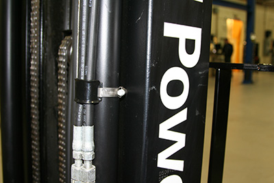
A piping installation is not complete until it has been properly clamped.
Rotary motion — Swivel or rotary joints are commonly used to provide rotating motion. Where rotary movement is a continuous 360°, use a rotary joint. If movement is reversing, a swivel joint would be the better choice. When used with hose, a swivel joint will avoid hose twisting or bending at the fitting.
- Control oil spray — Fire protection must be used where hydraulic lines are routed near hot, potentially hazardous areas. This prevents oil from a broken line from spraying onto any potential source of ignition. There are several ways to accomplish this:
- Reroute the line through a tunnel made from steel tubing, channel, or angle iron.
- Install a sheet-metal baffle between the lines and potential ignition source.
- Route the lines through a large, open-ended hose or sleeve so the oil will flow out of the ends in case of line failure.
- Use fire sleeves either to fit over the hose or built into the hose cover.
- To guard against a failed hose that might whip and spray hydraulic oil over an ignition source, anchor the hose to the component to which it is hydraulically connected.
- Minimum bend radii — The hose must be routed to accommodate the minimum bend radii of that hose. Minimum bend radii for various size hoses can be found in SAE
specifications and hose manufacturers’ catalogs. These figures usually refer to the minimum bend radius at maximum operating pressure for a static line. Exceeding the minimum
bend radius can result in kinking of the hose and/or most likely, extra stress at the hose or fitting interface. This causes the cover to become more easily cracked or the internal wire reinforcement to fatigue quicker, both of which will reduce service life. -

To avoid abrasion as much as possible, properly route and clamp the hose or use a protective cover.
Avoid abrasion — Most hydraulic hose is built with a tough outer cover to protect the hose reinforcement from abrasion or moisture damage. However, constant abrasion at one point will eventually puncture the outer cover and weaken the reinforcement. This is the number one cause of hydraulic hose failures in the field. To avoid abrasion as much as possible, properly route and clamp the hose or use a protective cover. Choose from a variety of protective coverings:
- Coiled springs
- Spiraled plastic
- Coiled strap steel
- Nylon sleeves
- Clamping — A piping installation is not complete until it has been properly clamped. Clamp choice is very important, and often it can be critical to the installation. Common sheet metal clamps will not hold a large, high-pressure hose.
Good clamps can be inexpensive, yet highly effective for high-pressure surge lines. Anticipate and plan for a possible length change ranging from an increase of 2% to a decrease of 4% for high-pressure lines. Properly sized clamps should grip the hose in a positive manner. To keep the clamp from abrading the hose, the ID of the clamp should be about 1⁄32 in. smaller than the OD of the hose.
Good installation techniques are essential to efficient operation and obtaining the maximum life of a hydraulic system. However, hydraulic hose and tubing are fatigue items with a finite service life. Eventually these wear items will fail. Typically, basic maintenance techniques are not enough to sufficiently prevent failures from occurring, whether it be visual inspection or time-based preventive schedules.
Eaton Corp.
eaton.com
Filed Under: Hose Assembly Tips
