
By Josh Cosford, Contributing Editor
Hydraulic motors are powerful and energetically dense rotary actuators with designs as versatile as their applications. As a hydraulic designer, you should know how to select a hydraulic motor that best suits your machine, balancing performance, price, and reliability. The range of options is vast, but this guide will steer you through the selection process to find the model best suited for you.
Calculating the torque required from a hydraulic motor is quite a bit more involved than with a cylinder, but we’ll work through a couple of examples together. For simplicity, we will start by running the calculations for a winch application before moving on to a drive wheel application. We’ll limit the number of variables, where possible, while still explaining the concept and math effectively.

internal gear mechanism of a hydraulic motor
Important math calculations
A winch is a simple hydraulic machine that uses a hydraulic motor to rotate a drum to reel in a cable or rope. Some employ a gearbox, but we’ll stick to direct drive winch motors for now. You must first select the force required from the pull of the cable, described conveniently enough as line pull. If you wish to pull or lift 10,000 pounds, for example, your line pull is 10,000 lb if we ignore any complexities added by pulley blocks. We then must calculate the torque on the drum where the cable lies:
T = F x r
T = F x rT = Torque at drum (foot pounds)
F = Line pull (pounds force)
r = Drum radius (feet)
The drum radius varies based on its cylinder diameter and the combined thickness of the cable wrapped around it. The larger the radius, the more torque is required to rotate the drum for any given line pull, so your calculations must factor in the layer build of the stacked cable. A full drum requires more torque, so make your calculations accurately and avoid assuming the torque is the same as with an empty drum. One more thing – if your winch needs to pull a thing, be sure that thing is part of your equation. Whether an anchor or a load of concrete, it must be contained within your line pull figure.
Using this math and a drum radius of 1.5 ft, our required torque is 15,000 ft-lb. However, as you’d guess, that’s just a raw number subject to detrimental factors, such as inefficiencies and a safety factor. If you plan to pull exactly 10,000 lb, offering a hydraulic motor rated for a theoretical 15,000 ft-lb would be a dangerous proposition.
Imagine an overhead crane running on the hairy edge of performance with a construction crew working 100 ft below. Depending on the industry you operate in, you need to apply a safety factor of 1.2 to 2.0, ranging from off-road winches to overhead cranes. Say our winch is designed for marine use, and we use 1.5 as our multiplier, which results in 22,500 lb-ft of torque. This extra fudge factor should include inefficiencies of the drum itself, such as the bearings, couplings and possible sealing elements.
22,500 lb-ft is a respectable amount of torque, especially considering there’s no gearbox involved, but now we know what we need from our hydraulic motor. The most important consideration is ensuring that the motor’s actual output matches your requirement. It sounds easy, but because the efficiency of a hydraulic motor varies widely with pressure and speed, you must select the displacement for the worst-case scenario. Unlike hydraulic pumps, which often follow a rule of thumb for efficiency, hydraulic motor data sheets are sometimes published with performance curves that show the sweet spot for efficiency at a particular speed and pressure. (Yes, these curves are also available for pumps, but they’re often closely guarded secrets.)
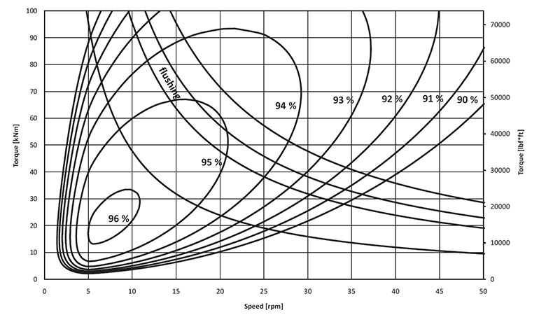
Figure 1 is a performance curve that compares torque (pressure) with speed (rpm), and shows where the motor is happiest running.
The example in Figure 1 is a performance curve that compares torque (pressure) with speed (rpm), and shows where the motor is happiest running. You can see that between 10,000 and 25,000 lb-ft and 5-12 rpm, this motor is 96% efficient, which is extraordinary. Without knowing more, we can see that this motor would be pretty good for our winch application, where it will be highly efficient during normal operation but also packs plenty of room to spare in the safety factor department.
Many of you already know you’re looking at the curve for a radial piston motor, which can produce monstrous torque with remarkable efficiency. However, not every motor manufacturer publishes these curves, especially for some of the lower-cost options.
Gerotor and disc valve motor manufacturers proudly publish the performance data for the world to see, despite less-than-stellar efficiency. Their data is arranged in grids, so you’ll have to calculate efficiency manually, but if you can find the exact sweet spot, you can achieve 85% efficiency or higher. Also called orbital motors, these units can easily drop to below 50% efficiency when operating outside their ideal range.
Besides these two examples, and because pump curves are unavailable, you must make assumptions surrounding efficiency. Other motor options are the gear (80% efficiency), vane (85% efficiency), and axial and bent-axis piston (90% efficiency) designs. These can vary, so check with your preferred manufacturer. Regardless, we need to use efficiency numbers in the selection of motor displacement, which is calculated as such:
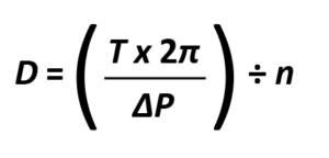
D = Displacement (in.³)
T = Torque (in.-lbs)
∆P = Pressure drop (psi)
n = efficiency (%)
You’ll notice that we switched to in.-lb for torque, which is done to keep the units consistent in the formula, as we don’t specify motor displacement in cubic feet per revolution. Multiply by 12 to get inch-pounds. Additionally, instead of just discussing the pressure available at the motor’s inlet port, we must subtract any pressure at the outlet port, which is why the “delta” is described above in terms of pressure drop. Running through the above winch motor example, which requires 22,500 ft-lb of torque and assuming we have 3,000 psi of pressure drop while using that sensational 96% efficient motor, we arrive at around 589 cubic inches of displacement (or about 9,600 cm³). I told you it was big.
Although not part of the motor selection process, consider that this motor will require over 260 gpm of flow to reach a reasonable-for-a-winch speed of 100 rpm. The calculation for motor flow requirement is opposite to that of pumps, as follows:
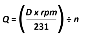
Q = Flow (gpm)
D = Displacement (in.³)
rpm = Revolutions Per Minute
231 = Cubic inches in a gallon
n = Efficiency (%)
Increasing complexity
We’ve come this far, and we’ve learned to calculate the torque, displacement and flow requirements of a hydraulic motor for a winch application. But what if you’re building something like a hydraulic ROV, then we’ll have to kick the complexity up a notch:
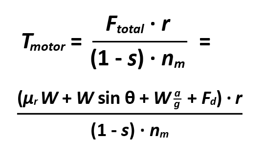
T = Torque required
Ftotal = Total Force
r = Wheel radius
s = Wheel slip
nm = Motor efficiency
µr = Rolling resistance coefficient
W = Weight of vehicle
a = Acceleration required (ft/sec²)
g = Gravity (32.174 ft/sec²)
Fd = Drawbar force
You can see that total force is equal to

which is, in order, rolling resistance, grade resistance, acceleration force and drawbar pull. It’s a lot of math, but it’s not hard math unless you’ve forgotten how to do trigonometry (which is required for the hydraulic specialist certification, anyway).
We can’t work through every single step and variable here, and we don’t want you to glaze over this article trying to follow along with grade 8 math. We can make some assumptions as far as variables go, however. If we build up an example, let’s go on the generous end of the variable range to ensure we have appropriate torque to overcome modest obstacles.
Rolling resistance: Let’s assume soft ground and apply 7% of the vehicle’s weight to soft tires (a coefficient of 0.07).
Grade resistance: We’ll say a 10% grade should be overcome, such as you’d see driving a golf course.
Acceleration: Our hydraulic ROV is not a drag car, so let’s cap acceleration at around 3 ft/sec².
Wheel slip: Since we have soft tires on soft ground, let’s say 10%.
Motor efficiency: A fixed displacement axial piston motor sounds good, so let’s say 90% here.
Weight: We’re just building a generic prototype for fun, so let’s say 1,500 lb.
Wheel radius: I think a 30 in. tire would be perfect, so let’s say 1.5 ft radius here.
Drawbar force: Let’s just keep the trailer out of the picture for now – vehicle and operator only.
Plugging it all in, we arrive at around 732 lb-ft of torque from our axial piston wheel motor, which is a respectable amount. Running the displacement numbers discussed earlier, and ignoring the efficiency because it has already been factored into our calculation, we will need an 18.4 in.³/rev motor (or approximately 300 cc/rev). I should mention that there are many ways to calculate vehicle drive force, many of which require multiple steps; however, this version is the most compact. Regardless, if you come across another method, it’s okay to use that one as well.
Motor type considerations
Once you’ve calculated your required hydraulic motor displacement, you can review the available types to determine which one suits your application and budget. As mentioned earlier, our options are gear, orbital, vane and piston. Not every option is available in the sizes you may need, so be sure to check manufacturer literature to confirm what is available.
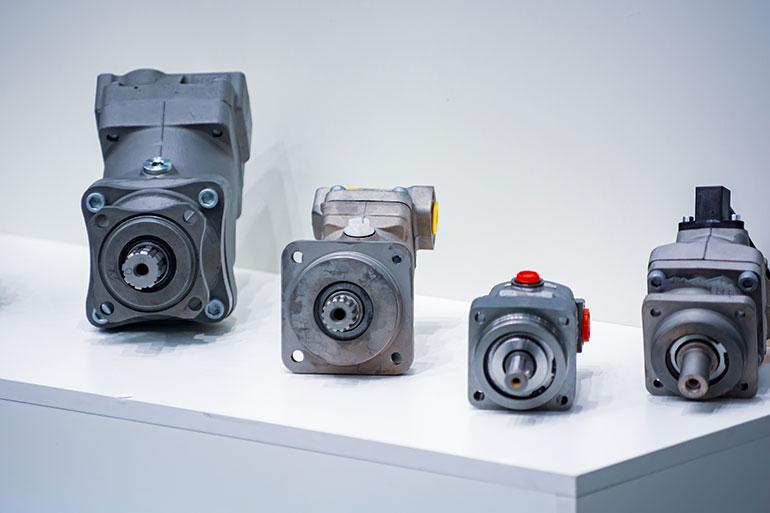
a selection of hydraulic motors
Image courtesy of Adobestock
Gear motors are the most basic design and are essentially gear pumps that include an upgraded shaft seal for unidirectional versions, allowing them to handle the pressure in both ports. Bi-rotational gear motors may use check or shuttle valves to bleed pressure to the opposing port, as internal leakage may otherwise build to a dangerous level.
Believe it or not, gear motors also offer respectable high-rpm operation, with many capable of 3,500 rpm or more. Their economical cost of entry is also a benefit, although the downsides reflect the price point. They offer generally poor efficiency, even when brand new, although they’re very reliable and resistant to contamination. They stake a claim to the smallest size, easily down to a fraction of a cubic inch displacement, and some manufacturers offer upwards of twelve cubic inches per revolution or more.
Vane motors are an interesting group, offering all the same benefits as their pump siblings: quiet operation, decent efficiency, and a wide range of sizes. Many are based upon their pump counterparts, so expect the same appearance as the venerable units that have proliferated in steel mills for the past five decades. They are easily repairable, and specific designs are easily modified to change the orientation of their ports. Expect a price point midway between gear pumps and piston pumps, but possibly lower if you opt for the knockoff versions.
Piston motors offer the broadest range of displacements, the most varied control systems, and the most specialized applications. Axial piston, bent-axis, and radial piston motors offer the highest power density due to their high-pressure capacity, which ranges from 5,000 to 10,000 psi. They range from tiny fixed-displacement designs to monstrous 13-liter units capable of twisting the Empire State Building.
The axial piston motor features a rotating group that spins around the shaft, while the pistons reciprocate parallel to the shaft. A fixed-angle swashplate controls the depth of stroke, and displacement is a factor of the number, diameter and stroke distance of its pistons. Variable displacement axial piston pumps are less common, perhaps because of their “medium duty” pressure rating (if you consider 5,000 psi medium-duty), but look for these as an excellent option for hydrostatic wheel drives with integrated hubs. Because axial piston motors are less popular, they’re not available in a wide displacement range, such as other designs.
The bent-axis piston motor is a high-pressure, high-speed design with a fixed- or variable-yoke angle, and a side-load-resistant design suitable for pulleys or gears. They’re offered in many variations for general-purpose or wheel-motor applications ranging from 5 cc (0.3 in.³) to over 1,000 cc (61 in.³), and capable of over 7,000 psi and 11,000 rpm in extreme examples. One particular manufacturer offers a 5 cc version that offers over 35 horsepower in a package that will fit into your coffee cup.
Radial piston motors wear the crown if charged with ruling the land of power and expense. For (mostly) slow, high-torque applications, such as winches, wheel drives, and crushers, nothing else comes close. They’re inherently capable of high pressure, and like all high-pressure pumps, they are sensitive to particle contamination. Radial piston motors, with a few exceptions, aren’t available as variable-displacement and are relatively devoid of advanced control features outside of braking systems or multi-speed control. Don’t even look at these if your application calls for small displacement, but for everything else above a thousand cc’s, this is pretty much your only option.
No discussion on motor types is complete without the orbital motor. Also called gerotor motors, these are a unique design and are essentially a type of inside-gear motor, where the inner rotor and outer ring gear rotating as directed through one of various internal valve functions. Available from a tiny 0.3 in.³ to a massive 75 in.³, they cover the torque and speed range requirements for most motor applications. They use various valve technologies to port fluid sequentially to create power; spool valves, disc valves or various other designs, they’re actually quite clever.
They’re highly economical, readily available and easy to install, but come with the downside of poor efficiency, especially when run outside their ideal pressure and speed range. They’re commonly found in mobile machinery and are also available in specialty applications such as wheel drives with integrated braking functions.
With so many hydraulic motor options, it may seem overwhelming to choose any given design. However, when you work through the math, consider your unique requirements and then factor in your budget, the ideal design will ultimately come down to a couple of realistic options.
Filed Under: Components, Engineering Basics, Pumps & Motors
