
As an engineer, hydraulic specialist or budding designer, knowledge of the various hydraulic pump options is imperative to provide your company or customers with the best possible option for any given machine. Despite personal preference for each pump type, dismissing any given design can potentially reduce system effectiveness or result in excessive costs. A gear pump, for example, may be a poor choice for a high-performance system, while a load-sensing piston pump is overkill for a bin tipper.
In many cases, the hydraulic circuit will dictate the pump choice, and it’s during the initial planning stage that the type of valves specified will jibe with the pump requirement. And it’s perfectly fine to use inexpensive parts to build inexpensive equipment, so simply selecting the most economical options makes sense when the customer understands they’re not buying a Rolls-Royce. Meanwhile, some complex valve circuits simply won’t function with a fixed-flow gear pump, such as those required when using mobile valves with load-sense technology.

Gear pumps are inexpensive, reliable, and resistant to contamination but are the least efficient and noisiest pump design.
All images courtesy of Josh Cosford, taken from The basics of hydraulic pump technologies webinar
This designer’s guide to pumps will help you select the hydraulic pumps that are best suited to your application, factoring in flow, cost, controls, and efficiency. Before selecting your pump, you must first calculate the required flow rate based on the ideal velocity of your actuators. There are two ways to calculate the raw flow.
Calculating raw flow
Cylinders: Q = (A x v/231)
Q = Flow in gpm
A = Area in.3
v = Velocity in./min
231 = in.³ in a gallon
Motors: Q=. (D x N)/231
Q = Flow in gpm
D = Displacement in.3
N = rpm
231 = in.³ in a gallon
After you arrive at your raw flow numbers, you’ll have to factor in things like acceleration/transients and efficiency. While being sure that working pressure was first calculated with sufficient extra pressure to help with acceleration, adding a bit of flow margin will also help with cycle times, especially with cylinders. A figure of 10-30% extra is a good start for constant cycling, although with infrequent yet rapid traverse, look into an accumulator to handle the extra buffer.
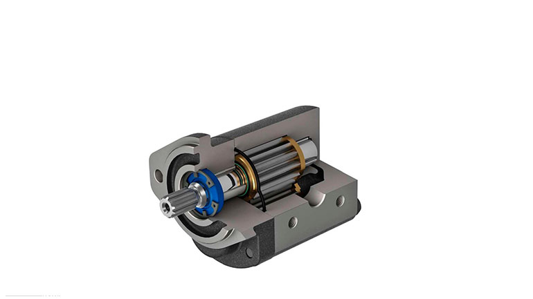
Internal look at a gear pump design
Although hydraulic cylinders are nearly 100% efficient, motors experience a wide range of fluid lost through leakage and lubrication. Expect only 60-90% efficiency for motors ranging in order of efficiency from low-speed high-torque gerotor style, gear motors, vane motors and then piston motors. The percentage of fluid lost to inefficiency must be added to the pump flow rate to compensate. So, if the theoretical flow of 10 gpm meets the rpm requirement, divide by the efficiency. For example, 10 gpm ÷ 0.60 = 16.7 gpm for gerotor motors, or 10 gpm ÷ 0.90 = 11.1 gpm for piston motors. These two examples demonstrate the importance of selecting an efficient design.
Once you’ve calculated your flow requirement, you can now calculate your pump displacement. Remember that pumps also experience both mechanical and volumetric inefficiencies, the scope of which depends on the pump type. Given that, you must factor efficiency when deciding your pump’s displacement, but otherwise, it’s calculated essentially the opposite of motors.
Pumps: D = (gpm x 231)/rpm
D = Displacement in in.³
gpm = Gallons per minute
231 = Cubic inches in a gallon
rpm = Revolutions per minute of the prime mover
Going back to our previous example of the 10 gpm gerotor motor, let’s say we’re looking for 1,000 rpm (take your time and cross-reference the formulas). Our 60% efficiency crutch means we need to throw 16.7 gpm at a 2.31 in.³ motor (ignore pressure for now). To make up for the energy lost to the gerotor, let’s spec an axial piston pump operating at 90% efficiency run via a 1,750 rpm industrial electric motor. Keep in mind that speed from engines will vary, but it’s always safe to base your math on the rpm where your engine produces the lowest brake-specific fuel consumption.
Running the calculations, once again, our theoretical flow rate to determine displacement is 18.6 gpm after we factor in the efficiency rating. And then again putting the 231 in.³ into the mix (because we don’t rate pumps by gallons/revolution) and then the speed of the motor, we arrive at just under 2.5 in.³ of pump displacement. Many piston pumps are described in metric, so multiply by the constant of 16.4 to arrive at around 40 cubic centimeters per revolution.

Internal design of a hydraulic vane pump
An overview of pump types
Let’s start fresh now that you know how to calculate your required pump displacement, because you have a few pump options to choose from. Gear pumps are the most economical choice, and operate using two spur gears installed in a pump body. With one driven and one idle gear, the prior motivates the latter as fluid is pushed around the circumference of the pumping chamber to create pressure and flow. While we’re on the topic, always remember that pumps create pressure, which allows flow to occur and not the other way around.
Gear pumps offer the widest range of displacement, from tiny fractions of a cubic centimeter all the way into the hundreds. They are the most resistant to contamination and enjoy the most lax contamination control protocol. However, they are very inefficient, even when new, and will only go downhill as they wear. They may include valve trickery, such as unloaders, but for the most part, they are simple and have fixed displacement. I should mention that the inside gear pump is highly efficient, but it comes with the penalty of an exponential investment cost compared to the outside spur gear style.

Vane pump illustration shows internal design
Vane pumps are a popular industrial pump choice because they are quiet while still reasonably priced in their fixed-displacement variant. They offer higher efficiency than gear pumps, but be prepared to pay two or three times the cost for fixed-displacement versions. Variable displacement vane pumps are popular in the machine tool industry, where they provide inexpensive pressure-compensated function in small to medium flow applications. You can find higher-flow, higher-pressure variable displacement vane pumps, but considering how expensive they are, it might be better to look at piston pumps unless you absolutely require a quiet option.
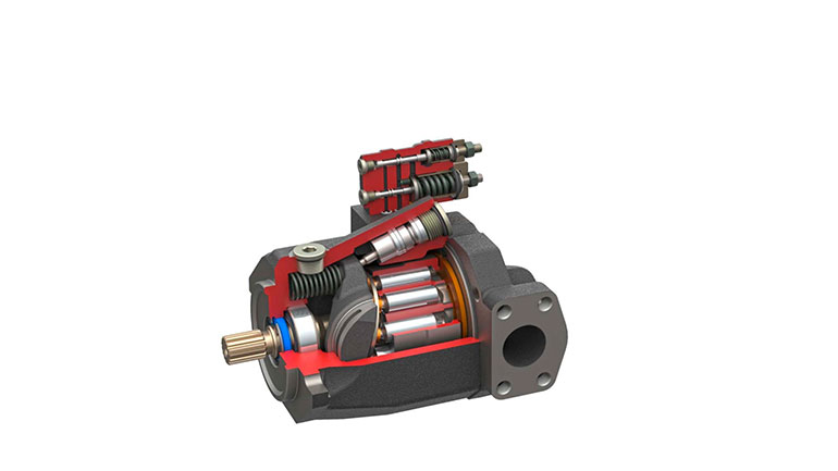
Internal makeup of piston pump
Piston pumps are the most efficient of the Big Three, but they come with a considerable price handicap, especially as you step up to the more advanced control systems. They’re also the most varied, not just in construction, but also in methods of compensation and control. Outside of specialty pumps, they generally range from around 5 to 1,000 cc per revolution or higher. You know the math for displacement, but let’s explore what other features are important to the designer.
There are three popular types of piston pumps: the axial, bent-axis and radial designs. The bent-axis piston pump has a (normally) fixed angle between the input shaft and the rotating group of pistons. The design includes a strong shaft bearing assembly that makes the motor highly resistant to side-load and suitable for very high speed, such as engine-powered applications. A few manufacturers make a variable-displacement version, although they are uncommon; most pumps are fixed-displacement. If you want highly reliable, reasonably priced access to high-speed, high-pressure pumps, consider the bent-axis version.
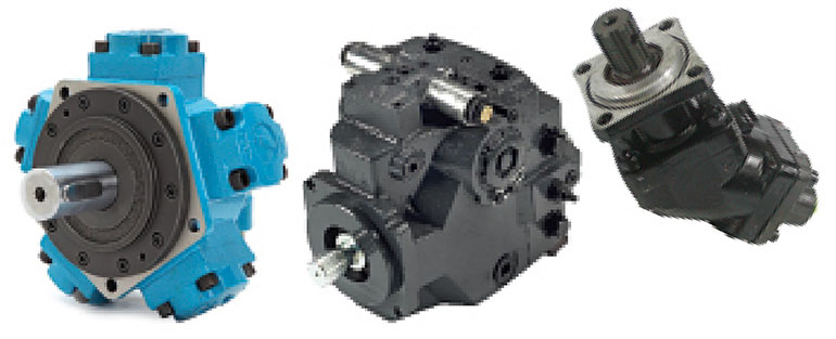
Left to right: Radial, axial and bent axis piston pumps
The radial piston pump sits atop the throne of high efficiency, with many designs returning 95% efficiency. Their WWI airplane engine appearance inherently converts linear force into rotational force with minimal waste product, and is also available in variable displacement versions. Their limitations are two-fold: the triple-thick manhole cover size and weight for larger displacements, and the expected financial capital to purchase a hydraulic pump the size of a triple-thick manhole cover.
By a wide margin, the most popular piston pump is the axial piston variety, which comes in the (rare) fixed-displacement and (common) variable-displacement siblings. The latter uses an adjustable swashplate tilted by a control piston to vary the stroke length of the rotating pistons. Their pistons reciprocate in parallel with their rotating shaft, offering the most compact package possible, considering their extensive list of features.
Control technologies for piston pumps
I could write a book on the various control technologies available for variable displacement piston pumps, but I’ll do my best to explain the basics. One thing in common with most of these is their requirement for closed-circuit valves, which block flow in their neutral state. The basic pressure-compensated version uses what is essentially a relief valve to direct pilot pressure to the control piston, which pushes hard against the swashplate to counter the bias spring/piston, which is attempting full displacement. Should the flow rate encounter enough resistance, say, 3,000 psi worth, the compensator will direct more pressure to the control piston to reduce swashplate angle to reduce displacement until there is equilibrium.
The second most common control method adds load sensing to the pressure compensator function, which uses a series of pilot lines that measure pressure downstream of any metering elements (flow controls or proportional valves) to maintain a particular pressure drop. Whereas pressure compensation alone stuffs its entire spring value worth of energy in the system to create flow (e.g., 3,000 psi), load sense provides only enough flow to maintain the 300-400 psi of pressure drop equal to its setting.
Such a system is astronomically more efficient, although it comes with the cost and complexity required to acquire a pressure signal from every workport line in the system. As such, these are often limited to systems using specialized valves (like sectional mobile valves) or custom manifolds using check or shuttle valves neatly ported inside.
Pressure compensation and load sensing are, by far, the two most common types of control. Still, there are many useful options that you should be aware of. If your machine is limited in horsepower due to emissions standards, yet you want the best of both worlds in terms of pressure and flow, select the horsepower-limiting pump. This option is capable of high flow or high pressure, but will restrict total power output to prevent them from occurring simultaneously, and will do so seamlessly. Nearly all excavators, for example, use a horsepower control pump to enable rapid work functions when loads are low, but can ramp up pressure while slowing down speed to overcome heavy loads.
Less common, although widely available, are electric or electroproportional control of pumps. From simply using a directional valve to switch between two different pressure settings on two different compensators, to servovalves that operate alongside closed-loop electronic control to vary pressure and flow precisely. Remote compensation uses a separately plumbed relief valve directing its pilot line to the pump so that pressure is easily adjusted away from the pump. The relief valve could be either knob-operated or electroproportional. Before we conclude on controls, remember that some vane pump designs come with several of these options.
Installation and plumbing tips
Now that you’ve selected your pump type, along with its displacement and control option (if applicable), the designer must know how these are installed and plumbed. Fundamentally, the principles are the same, despite geographical variations – you need to mount the pump, drive the pump and then connect the plumbing.
Pump mounting in North America is primarily a variation of the SAE J744, which defines the flange bolt pattern, shaft type and pad interface. The flange comes in 2- or 4-bolt configurations, with bolt centers ranging from 3.25 to 12.5 in. (on large pumps). For heavier pumps, the 4-bolt design is recommended to manage the overhung mass better. The pilot of a pump is a critical design element preventing shaft misalignment. The pilot is a cast or machined counterbore that inserts into the mount or bell housing, avoiding the time-consuming radial and axial alignment techniques of yesteryear.
For metric options, it’s less streamlined for pump mounting flanges and shafts, as the standards for mounting flanges may differ from the pump standard. Nevertheless, the ISO 3019-2 standard is a cousin to the SAE J744 and describes the flanges and shafts on most pumps on the overseas market. For ISO mounts, many pumps use a rectangular flange, although the bolt centers and pilots will be entirely different from those of SAE Mounts.
What’s common is the need for a bellhousing (pump/motor mount) that conjoins the pump and prime mover while offering a central space for the shaft connection. Many manufacturers of power unit components offer various standard mounts for a variety of NEMA and Metric motors, which themselves employ a bolt circle and pilot to oppose the pump’s. The distance between each flange face accommodates the shafts, which themselves are connected to one another with couplings. Ensure that you calculate the combined lengths of the pump and motor shafts with sufficient room to accommodate the polymer insert.
Bellhousings are offered in horizontal and vertical styles, which are selected based on the type of reservoir used on its power unit. The horizontal type must be strong enough to hold the (sometimes heavy) pump in free air. The vertical type often coincides with the in-tank pump mounting method on vertical reservoirs, where it actually sits within the oil. Be sure to select the correct pilot and bolt centers that match your reservoir.
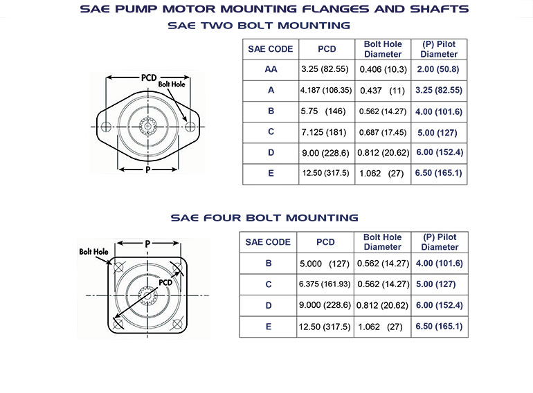
Pump mounting in North America is primarily a variation of the SAE J744, which defines the flange bolt pattern, shaft type and pad interface.
Your final criterion for selection is the port and plumbing standard. This requires less lengthy discussion since you’ll likely just choose what’s appropriate for your locale: SAE ORB or Flanges for North America, BSPP or Flanges for Europe, and the rest of the world will vary. As a designer, avoid tapered ports and, if possible, use flanged ports to make installation easier, as fitting and hose orientation are less critical during installation. Otherwise, just select what is popular in your area.
Selecting the perfect pump for your hydraulic system ensures you can balance the best combination of performance, price and maintainability. With so many options, it’s easy to be paralyzed by choice. However, if you follow this designer’s guide and work through each criterion, your biggest challenge will be how quickly you can get it.
Filed Under: Components, Engineering Basics, Pumps & Motors
