
Hydraulic flanges may look simple from the outside, but they are among the more technically demanding connection points in a hydraulic circuit. A flange is far more than a method for attaching hose or pipe to pumps, valves or manifolds — it is a pressure-containing interface whose dimensions, geometry and material selection directly affect system reliability, maintenance and safety. Seemingly small specification errors can create major performance and compatibility issues.
Understanding the application
At the most basic level, a hydraulic flange serves as the connection between hydraulic components and piping or hose assemblies. Yet specifying the correct flange requires much more information than simply choosing a nominal size.
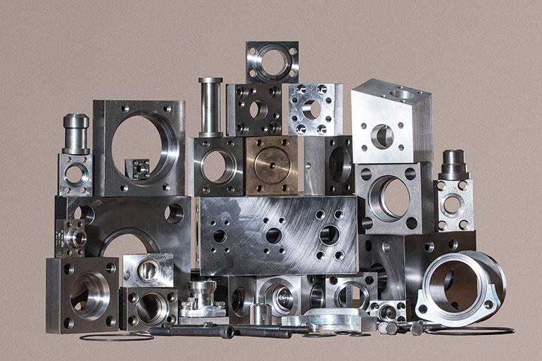
According to Robert Mackey, General Manager of Main Manufacturing Products Inc. and expert on the SAE J518 standard, engineers typically need nine key pieces of information to properly specify a flange:
- Pad size
- Bolt size and type
- Material
- Connection type
- Connection size
- Pressure rating
- Geometry
- Flange type
- Special features and other details, such as manufacturing origin
Many hydraulic systems today rely on SAE J518 flanges, which account for the majority of hydraulic flange usage worldwide. These rectangular four-bolt flange connections are technically aligned with ISO 6162 standards and remain the dominant standard across North America and many global markets.
However, engineers also encounter DIN, JIS, CETOP and proprietary flange configurations depending on the machine manufacturer and regional standards requirements.
Nominal sizing can create confusion
One of the first challenges in flange specification is understanding nominal sizing terminology.
Hydraulic flange sizes are commonly referenced by dash size in inch-based systems or by DN (designation nominal) in metric systems. For example, a 1-in. flange connection may be called a -16 flange or DN25.
But nominal sizing does not represent an exact physical measurement. As Mackey explained, nominal dimensions are simply naming conventions that group together a standardized set of dimensions and tolerances. Like pipe sizing, there may be no actual dimension that precisely equals the nominal size. This becomes particularly important when engineers attempt to identify an existing flange in the field.
Accurate measurement is critical
Flange sizing errors frequently occur because multiple flange standards can appear visually similar while having slightly different bolt patterns or dimensions.
Mackey emphasized that engineers must carefully measure bolt hole spacing and bolt circle dimensions — often within 0.005 in. (0.1 mm) — to ensure proper identification. Even small dimensional differences can create compatibility problems between standards.
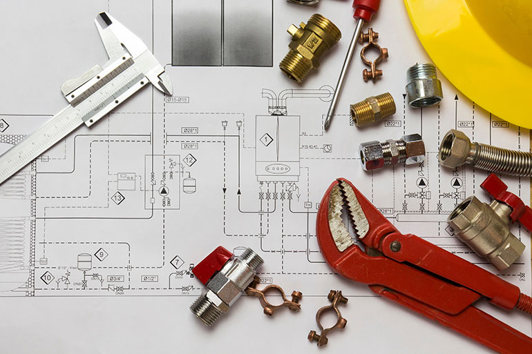
The challenge becomes greater because manufacturing tolerances themselves may vary by approximately 0.010 in. or more. A flange that appears close enough visually may still fail to seal correctly or align properly under pressure.
One practical recommendation involves measuring bolt hole spacing using digital calipers by zeroing on the bolt hole diameter and then measuring outside-to-outside dimensions. This approach helps simplify identification while improving accuracy.
Pressure ratings depend on more than size alone
One of the most common misconceptions in flange selection is assuming that pressure capability depends solely on flange size. Generally the screw size and O-ring groove size will determine the pressure rating. The flange must attach to the port and the port will determine the pressure rating. The J518 standard provides pressure ratings for the ports.
Additionally, pressure rating is influenced by several interconnected design factors, including:
- Bolt size
- Bolt strength
- O-ring groove dimensions
- Flange geometry
- Material selection
- Port design
In many SAE flange systems, the port itself ultimately determines the maximum allowable pressure. Mackey also warned that geometry modifications can significantly alter load capacity. For example, removing one bolt from a four-bolt flange elbow might appear to reduce strength by only 25%, but the resulting torque loading can reduce effective strength by 40% to 50%.
This highlights why engineers should avoid modifying standard flange designs without understanding how those changes affect structural loading.
Choosing the right connection type
Sizing a flange also requires selecting the correct end connection. The connection type is important because it could be welded, threaded or flanged. Welded flanges include socket weld, butt weld and special weld grooved geometries. Threaded flanges include SAE straight thread, sometimes called SAE O-ring boss, BSPP and tapered threads which are BSPT and dry seal or NPTF (where the F stands for fuel). NPTF is a special thread that is interchangeable with, but not identical to the NPT thread.
Each option has advantages depending on the application. For example, the fluid power industry increasingly favors SAE straight-thread O-ring boss connections over tapered pipe threads because O-ring sealing offers improved leak prevention over time.
Socket weld and butt weld connections also require careful attention to pipe schedules, tube outside diameters and regional dimensional standards. Metric tubing can present additional complications because tube dimensions may vary between German, Japanese and Chinese standards even when nominally identified as the same size.
Geometry affects both flow and installation
Beyond sizing and pressure capability, flange geometry plays a major role in system packaging and maintenance accessibility.
Hydraulic flanges are available in numerous configurations, including:
- Inline connectors
- Elbows
- Run tees
- Branch tees
- Crosses
- Offset flanges
- Saddle welds
- Connector blocks
These configurations help engineers simplify piping layouts, reduce leak points and improve serviceability.
Offset flanges, for example, can help designers maintain full flow while accommodating tight clearances. Flanged elbows and adapters may reposition hose connections to improve maintenance access around pumps or accumulators.
Saddle welds provide another useful option by allowing a flange connection to mount directly onto the side of a pipe or reservoir rather than only at pipe ends.
O-ring versus flat-face flange designs
A critical consideration in hydraulic flange specification is whether the application requires an O-ring style flange or a flat-face companion flange. Most hydraulic systems today use O-ring flange designs because they provide more reliable sealing under high pressure. Modern captive O-ring grooves offer additional sealing force by containing the O-ring more securely within the groove geometry during compression.
Typically:
- O-ring flanges use clearance bolt holes
- Flat-face companion flanges use tapped holes
Flat-face flange heads are relatively uncommon but still exist in specialized applications. Engineers must ensure compatibility between mating surfaces because mismatched flange faces can prevent proper sealing entirely.
Material selection directly affects reliability
Material choice is another critical factor when sizing hydraulic flanges. Carbon steel remains the most common material for hydraulic flange construction, particularly low-carbon grades such as 1018 or 1025 steel that provide good weldability and pressure performance as well as improved surface finish.
However, many applications require alternative materials including:
- Stainless steel
- Aluminum
- Monel
- Hastelloy
- Inconel
- Duplex stainless steel
Mackey stressed the importance of using low-carbon “L” grades for stainless steel flanges, such as 304L or 316L, because they reduce the risk of corrosion and weld degradation over time. He also cautioned against using A36 structural steel for pressure-containing flange components, noting that it is unsuitable for pressure boundary applications despite its widespread availability.
Accessories can simplify system design
Specialized flange accessories can play an important role in improving hydraulic system performance and maintenance. Examples include:
- Flange adapters
- Gauge port adapters
- Connector plates
- Spacers
- Reducers
- Reservoir adapters
- Connector blocks
Gauge port adapters are particularly useful because they allow pressure measurement directly within a flange assembly without redesigning the hydraulic circuit. Flange adapters can also solve common compatibility issues such as converting between Code 61 and Code 62 flanges, rotating bolt patterns or adapting between inch and metric systems. These solutions often reduce downtime, simplify maintenance and minimize custom fabrication requirements.
Proper flange sizing reduces risk and cost
Although hydraulic flanges may appear to be routine components, they represent a highly engineered interface where small specification mistakes can lead to leakage, pressure loss, installation issues or premature failure. Accurate sizing requires engineers to evaluate standards, pressure ratings, geometry, materials and sealing methods together, not independently.
Filed Under: Hose Assembly Tips
