
By Josh Cosford, Contributing Editor
Hoop stress. It’s a real term, and it’s not discussed nearly enough in fluid power. Hoop stress describes the circumferential stress against a tube, cylinder or circular wall caused by internal pressure acting outward. If you visualize the steel bands that circle a wine barrel, you get the idea. But hoop stress tells us why microbore hoses, despite being plastic, are capable of astronomical pressure.
Hoop stress doesn’t scale linearly with diameter, and is inversely proportional to wall diameter:
σ = (P × D) / (2 × t)
σ = Stress
P = Pressure
D = Hose ID
t = Wall thickness
I know it’s math, but just relax and read it. What it means is that doubling the wall thickness has the same effect as halving the internal diameter, although this applies more to tubes, pipes and hoses than it would to an orifice, which is part of a different set of thick-wall pressure vessel equations. But that’s neither here nor there when we’re talking about microbore hose.
Microbore hose made from PTFE rated for 5,000 psi or more will often be about 1/8 in. (0.125 in.) ID with only 0.060 in. wall thickness. You read that right … just sixty thou’. The hoop stress scale tells us that if we want to double the diameter, we have to double the wall thickness if we wish to maintain the same pressure. Going up to ¼ in. ID means we now need 0.120 in. wall, and for ½ in. ID we have to jump up again to 0.240 in. wall thickness.
I think you get the picture, and now you see why it’s just impractical to manufacture high-pressure, large bore hoses, cylinders and pressure vessels. If you follow this formula, a 12 in. ID PTFE-based hydraulic hose would require nearly 6 in. thick hose and reinforcement, with an outside diameter nearly 24 in. Crazy, right?
Okay, so the relationship is clear, but why does it have to be this way? Why is wall thickness not absolute? Well, it’s surface area. Let’s picture a radial ring that is 2 in. ID and 1 in. wide, below. The area of that inner surface is circumference times width, which puts it at 6.28 in.² of surface area. At 3,000 psi, there is 18,840 lb pushing outward on that internal surface.
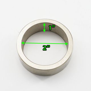
So let’s double the diameter and run it again. Circumference is Π x D, so with 4 in. diameter we now have about 37,699 lb pushing outward on that ring. If we extrapolate and compare to the 0.060 in. wall thickness of the and wish to run 5,000 psi as well, we’ll need nearly 2 in. wall thickness to resist the 63,000 lb pushing outward on our PTFE tube.
Of course, nobody with their head on straight is making 5,000 psi hydraulic cylinders with PTFE barrels, and it’s clear we don’t need 2 in. steel wall for a hydraulic cylinder of this strength. But the formula still applies as it does for microbore hoses. Here at Higginson, we use ¼ in wall honed steel tube for our 4 in. bore hydraulic cylinder (albeit rated for 3,000 psi with a 4:1 safety factor).
It stands to reason that an 8 in. bore heavy duty hydraulic cylinder would require ½ in. wall to contain the same 3,000 psi, and reason would be correct. I see no reason a 16 in. bore cylinder won’t be just fine with 1 in. thick wall, showing us that hoop stress math works out in most cases (admittedly, not all). So the next time you’re checking pressure after connecting those tiny little hoses to a test point, don’t stress knowing the outward forces are tiny despite thousands of pounds per square inch.
Filed Under: Components, Engineering Basics, Hose & Tubing, Hose Assembly Tips
