Fluid Power World

  • Home
  • Technologies
    • Hydraulics
      • Cylinders & Actuators
      • Filtration/Contamination Control
      • Fittings, Couplings & Adapters
      • Fluids
      • Fluid Conditioning
      • Hose & Tubing
      • Pumps & Motors
      • Related Technologies
      • Sealing
      • Sensors & Gauges
      • Valves & Manifolds
    • Pneumatics
      • Air Preparation & Regulation
      • Compressed Air Technologies
      • Cylinders & Actuators
      • End Effectors & Grippers
      • Fittings, Couplings & Adapters
      • Hose & Tubing
      • Sensors
      • Vacuum
      • Valves & Manifolds
  • Engineering Basics
  • Trending
  • Resources
    • Digital Issues
    • Distributor Search
    • Engineering Week
    • Podcasts
    • Videos
    • Webinars / Digital Events
    • White Papers
  • Leadership
    • 2020 Leadership in Fluid Power Winners
    • 2021 Leadership in Engineering Winners
  • Women in Engineering
    • Women in Fluid Power
    • Women in Engineering
  • Design Guides
    • Design Guide Library
    • Electro-Pneumatic Regulator & Flow Controller Design
    • Hydraulic Cylinders
    • Hydraulic Filtration
    • Hydraulic Hose Assembly
    • Hydraulic Pumps
    • Pneumatic Actuators
    • Pressure Gauges
  • Events
    • Engineering Week
    • Fluid Power Tech Conference

Linear position sensors help cylinders control air and fuel in blast furnaces and power plants

By Mike Santora | May 20, 2016

Share
balluff-image-SDC10576

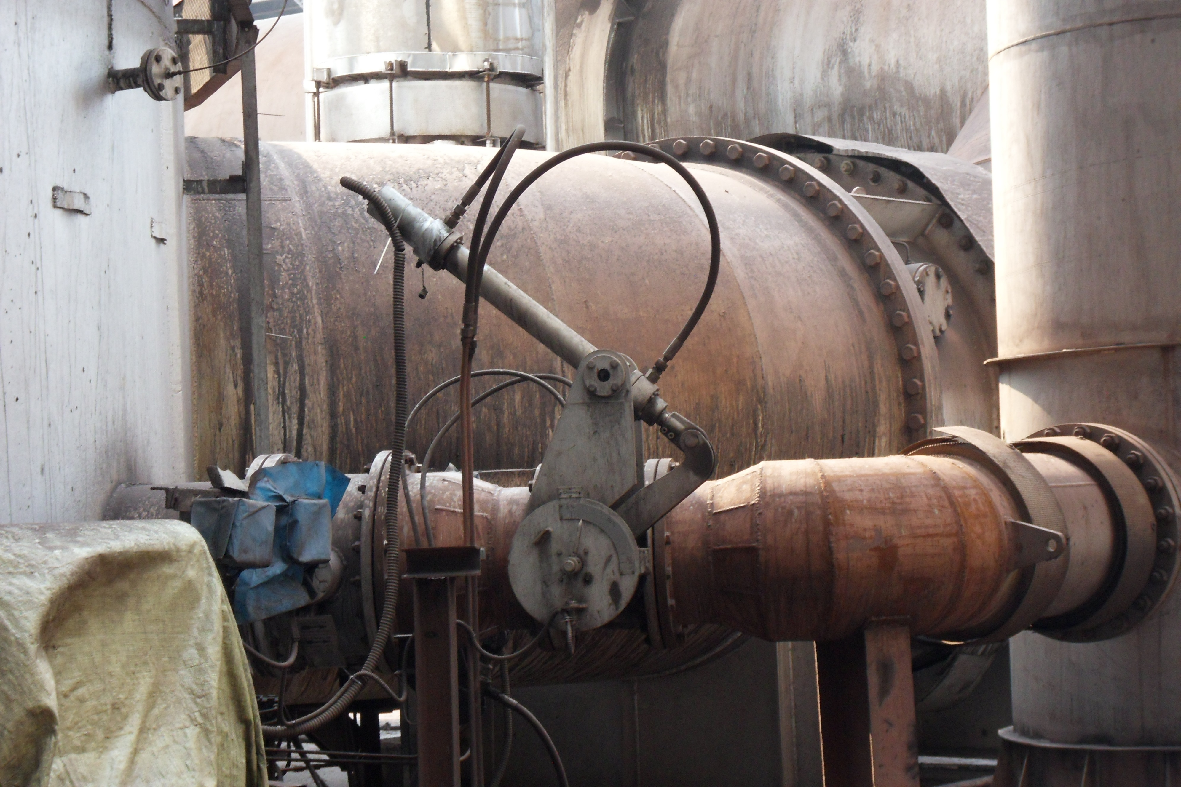
A hydraulic cylinder with a linear position sensor controls the position of a valve to regulate the flow of combustion air
entering a blast furnace producing iron.

A popular application for linear position sensors is hydraulic cylinder position feedback for valve actuators. The position sensor is installed into the back end of the cylinder. The sensing element rests in a cavity that has been gun-drilled through the piston and cylinder rod, extending the full length of the mechanical stroke. A magnet ring is then used as position marker and is recessed into the face of the piston and secured with screws or snap rings. When Balluff began designing one such design—its Micropulse linear position sensors—there were challenges that needed to be dealt with.

To tolerate the harsh operational conditions in these plants, cylinder position sensors must be able to withstand elevated levels of heat and continue functioning reliably. They must also be well sealed against liquid ingress across a wide range of temperatures and humidity, since many installations are exposed to seasonal outdoor weather conditions.

During the product design phase, the Balluff design team used a destructive test regimen called HALT (Highly Accelerated Life Test). This test subjects the sensor to rapid swings from extremely cold to extremely hot while simultaneously applying severe mechanical shock and vibration. The severity of the test conditions is increased until a failure occurs. The failure is then analyzed and the root cause determined. This failure mode is then addressed in the next design iteration with the goal of eliminating it or hardening the product to improve the survivability at even more severe stress levels.

webapplikation _9_Hochofen und Lichtbogenofen regelung 131202

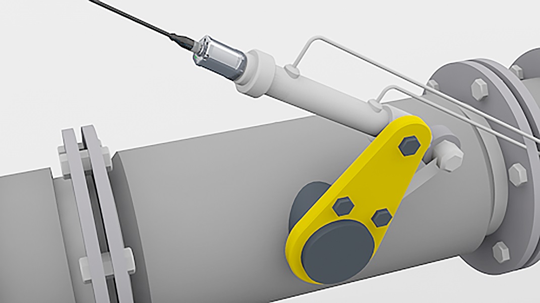
Illustration showing arrangement of hydraulic cylinder and linear position sensor on the combustion air valve.

Hydraulic cylinders drive flap and valve operation In any combustion process designed to produce large volumes of heat energy, efficiency and temperature control depend on the amount and proportion of intake combustion air and fuel being consumed under varying conditions of demand. Exhaust or “flue” gases must be managed as well, depending on whether they need to be bypassed to another process or sent to an emissions scrubber before being vented to the atmosphere. For example, in steel production and in conventional electric power generation plants, combustion air intake dampers and natural gas valves are controlled by hydraulic cylinder actuators. To regulate damper or valve position, the position of the cylinder must be monitored by a sensor that provides a feedback signal to the process control system. Micropulse linear position sensors are installed into the hydraulic cylinder actuators where they detect the position of a target magnet mounted to the face of the cylinder piston.

A linear position sensor is first and foremost a measurement device. It must provide an accurate and stable position signal across a wide range of adverse operating conditions. It’s one thing to create a measurement sensor that performs well in a laboratory, but it takes development and know-how to deliver a sensor that is both accurate and physically robust enough to stand up to adverse industrial conditions. 

Balluff
balluff.com

Other articles for you:

Balluff-BTL6 rod style linear position sensor with IO-Link 1.1Balluff launches in-cylinder rod-style linear position sensor with IO-Link Specially ruggedized linear sensors are designed to withstand impacts and vibration typical of sawmills.Improving the reliability of hydraulic cylinder sensors Linear transducers with redundancy increase uptime rates SIKO-Wire-actuated encoder SGH10Direct stroke measurement for hydraulic cylinders

Filed Under: Sensors
Tagged With: balluff
 

About The Author

Mike Santora

Current Digital Issue

Are hydrogen fuel cells the future for mobile machines? Prioritizing decarbonization is, without doubt, one that most countries agree with almost pure unanimity. Here, in the U.S., the Biden administration has a goal to eliminate carbons from the electric grid system by 2035. Globally, most countries are on similar timelines. But, looking ahead to 2050,…

Get Fluid Power News Direct

Fluid Power News

RSS Featured White Papers

  • High-force linear motion: How to convert from hydraulic cylinders to electric actuators and why.
  • A technical comparison: Performance of pneumatic cylinders and electric rod actuators
  • Quick Connect Couplings: A Critical Component in Hydraulic Systems

Follow us on Twitter!

Tweets by @wtwh_paulheney
Tweets by @FPW_MaryGannon

Fluid Power World 2021 Handbook

Fluid Power World
  • Hose Assembly Tips
  • Mobile Hydraulic Tips
  • Pneumatic Tips
  • Sealing & Contamination Control Tips
  • Advertise
  • About us
  • Contact Us

Copyright © 2022 WTWH Media LLC. All Rights Reserved. The material on this site may not be reproduced, distributed, transmitted, cached or otherwise used, except with the prior written permission of WTWH Media
Privacy Policy | Advertising | About Us

Search Fluid Power World

  • Home
  • Technologies
    • Hydraulics
      • Cylinders & Actuators
      • Filtration/Contamination Control
      • Fittings, Couplings & Adapters
      • Fluids
      • Fluid Conditioning
      • Hose & Tubing
      • Pumps & Motors
      • Related Technologies
      • Sealing
      • Sensors & Gauges
      • Valves & Manifolds
    • Pneumatics
      • Air Preparation & Regulation
      • Compressed Air Technologies
      • Cylinders & Actuators
      • End Effectors & Grippers
      • Fittings, Couplings & Adapters
      • Hose & Tubing
      • Sensors
      • Vacuum
      • Valves & Manifolds
  • Engineering Basics
  • Trending
  • Resources
    • Digital Issues
    • Distributor Search
    • Engineering Week
    • Podcasts
    • Videos
    • Webinars / Digital Events
    • White Papers
  • Leadership
    • 2020 Leadership in Fluid Power Winners
    • 2021 Leadership in Engineering Winners
  • Women in Engineering
    • Women in Fluid Power
    • Women in Engineering
  • Design Guides
    • Design Guide Library
    • Electro-Pneumatic Regulator & Flow Controller Design
    • Hydraulic Cylinders
    • Hydraulic Filtration
    • Hydraulic Hose Assembly
    • Hydraulic Pumps
    • Pneumatic Actuators
    • Pressure Gauges
  • Events
    • Engineering Week
    • Fluid Power Tech Conference