
These changes can unlock plant-wide air savings, avoid major capital investment, and improve carbon footprint.

Steve Bain, Industry Segment Manager, Food and Packaging, Festo
By Steve Bain, Industry Segment Manager, Food and Packaging, Festo
Compressed air is one of manufacturing’s largest energy expenses, and most plants run it far above what their machines actually require. By tuning machines that use excess compressed air rather than running at an unnecessary pressure, facilities can safely lower the compressor setpoint and save energy plant wide without capital expenditure.
The operating reality in most plants
Most compressor pressure settings are the result of a plant’s history — pressure was raised at some point to solve an immediate production concern and then never brought back down. Without an accurate record of what pressure each machine requires, the higher setpoint remains.
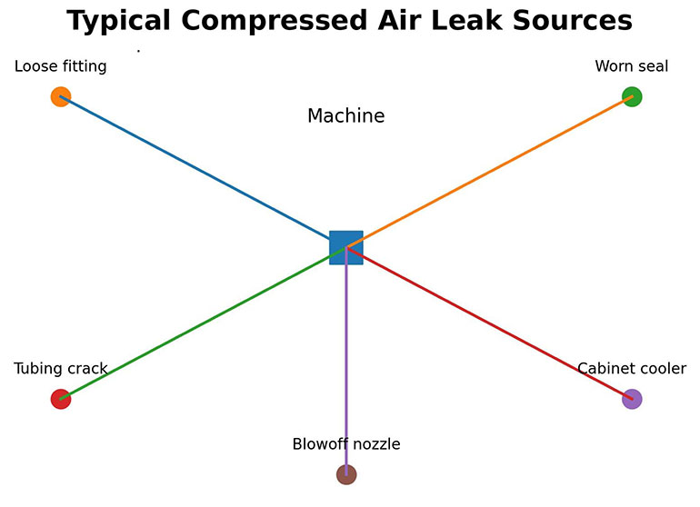
Leakage and unintended air use also increase the system load. A small fitting vibration, a worn seal, or a cabinet cooler left running may seem insignificant, but together they raise the plant’s baseline demand and force the compressor to work harder than the processes truly require.
Every plant also has a machine or process that is the “highest air consumer” and this is a limiting factor, effectively holding all the machines on a compressor at highest load. Until the highest consumer, the system’s underlying leakage, and unintended consumption are identified and corrected, the compressor cannot be lowered and the plant’s compressed air usage brought down to an optimum level.
Five low-cost practices for establishing true air demand at the machine level that help facilities reach maximum energy savings:
- Eliminate leaks and unintended air use
- Establish the true minimum pressure for each machine
- Identify peak-demand events and the limiting machine
- Reduce demand at the limiting machine
- Monitor the system to sustain the gains
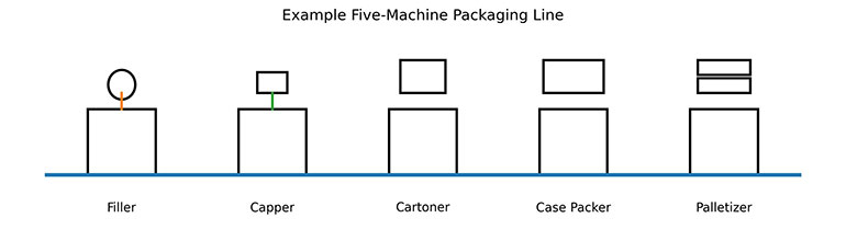
To illustrate these practices, visualize a five-machine production line consisting of a filler, capper, cartoner, case packer, and palletizer. Each machine in this illustration line uses compressed air differently, and together they represent the kinds of demand patterns found in most plants. The five practices will be used to lower plant-wide air usage without major expense or adding new capital equipment.
Practice 1: eliminate leaks and unintended air use
Leaks and unintended air use raise the baseline pressure the compressor must maintain, increasing energy cost long before the machines even begin to cycle. Much of this loss comes from worn seals, loose fittings, damaged tubing, or aging piping. Other losses are “designed leaks” that run continuously — vacuum left on during stoppages, cabinet coolers without thermostats, and blowoff air that never shuts off. These losses accumulate across shifts and make it appear that the system requires more pressure than it does.
For example, on the filler in the example five-machine line, a conveyor-side fitting leaked steadily. It was audible with an acoustic wand and immediately confirmed with the imaging tool. Fixing this single leak reduced the filler’s baseline draw, making it easier to lower the machine’s operating pressure in the next step.
Every leak fixed reduces the constant load on the compressor, improves system stability, and creates the headroom needed to safely lower machine and system pressure.
Practice 2: establish the true minimum pressure for each machine
Machines are often commissioned with regulators set slightly above their required pressure to ensure reliable operation. As the machine ages, seals, valves, and fittings begin to wear, and air escapes. Small leaks can develop in tubing and connections. Operators often respond by using the regulator to raise pressure to compensate for slowed or inconsistent motion. Over time, these adjustments create an upward creep that makes the machine appear to need more pressure than it truly requires.
To determine the true minimum pressure, a maintenance technician should turn down the regulator gradually until the machine fails to adequately perform its motion. The technician then raises the pressure slightly to establish a stable buffer and records the new setpoint. This reveals the machine’s real requirements at its current state of wear and configuration. The method is simple, safe, and costs nothing, but it must be done methodically so that each axis, gripper, cylinder, or vacuum device is tested under normal cycle conditions.
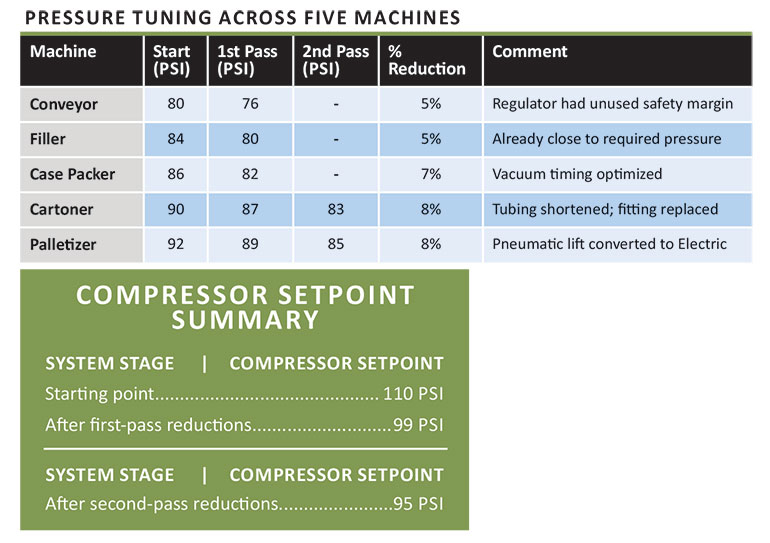
For example, on the cartoner in the five-machine line, a technician conducted the pressure test and confirmed that the cartoner can operate reliably at a lower setting, dropping from 80 to 76 psi.
Practice 3: identify peak-demand events and the limiting machine
Lowering machine pressures reduces overall consumption, but it does not reveal which machine creates short-burst, high-flow events that momentarily pull down system pressure. These peak-demand events are critical to identify and understand because the compressor must be set high enough to prevent a pressure sag during the heaviest motion on the line.
Peak-demand events may occur when a large-bore cylinder moves a load, when several actuators fire at the same moment, or when a vacuum circuit vents a high volume of air in a single release. A simple fix for an isolated peak event is adding a small reserve tank near the component that creates the momentary drop.

On the cartoner, for example, a reserve tank placed close to the large-bore lift cylinder supplies the burst of air needed for that motion while providing a buffer for the machine pressure. This low-cost step often stabilizes the machine without further changes.
With the peaks removed from the mix, the machine with the highest validated pressure requirement stands out as the limiting machine — the one that ultimately prevents further reduction of the compressor setpoint.
In the five-machine example, the palletizer now shows up as the highest validated pressure. Its large-bore cylinders consume a high volume of air during every cycle, and that steady requirement, not a momentary peak, establishes the palletizer as the limiting machine.
Practice 4: reduce demand at the limiting machine
Once the limiting machine is identified, the next step is to reduce the amount of air it requires during normal operation. Excessive demand on a limiting machine often comes from the design engineer, who may intentionally oversize cylinders to guarantee performance. A design with long tubing runs, which use more air, may have been chosen for convenience, and restrictive fittings, which increase pressure drops, may have been specified without consideration for their negative impact on air flow.
Demand on the limiting machine can be reduced by resizing cylinders, shortening tubing runs, replacing quick-disconnects with full-flow fittings, or converting high-volume pneumatic motions to electric axes. These are targeted updates, not machine redesigns, and they directly reduce the volume of compressed air required for each cycle.

In the five-machine example, the palletizer was identified as the limiting machine. Its lift function was originally handled by a large-bore pneumatic cylinder. Replacing this motion with an electric axis eliminated the cylinder’s high air demand. Once this change was made, the palletizer’s validated pressure requirement dropped, and it was no longer the limiting machine.
The line now had a new limiting machine, the cartoner. Maintenance performed the same targeted adjustments there — shortening a long tubing run and replacing a restrictive fitting — and the cartoner’s validated pressure dropped as well.
After fixing leaks and finding the true operating pressure of the five machines the pressure at the compressor was reduced from 110 to 99. Reducing instances of short high bursts and reducing the limiting machine allowed a second cut from 99 psi to 95 psi, a 14% overall decrease in plant wide air consumption and a 7.5% overall reduction in energy usage according to U.S. Department of Energy guidelines. By preventing pressure creep and maintaining a lower system load, the existing compressor may deliver more years of service, delaying or eliminating the need for a new unit while improving the facility’s overall sustainability profile.

Plug-and-play combinations of the D2M, module lower right, with a C2M, upper left, can monitor and improve the energy efficiency of two separate compressed air networks simultaneously.
When this process is completed across all five machines, the validated pressures can be compared side-by-side. Once these values are known, the compressor setpoint can be lowered to about 9–10 psi above the highest validated machine pressure, creating an immediate plant-wide savings. On the five-machine line, the compressor was running at 110 psi before leak reduction and individual machine repair. The compressor setpoint has now been reduced to 99 psi, a 10% reduction.
Practice 5: monitor the system to sustain the gains
Sustaining gains begins with disciplined monitoring. On a regular basis, maintenance personnel record each machine’s validated pressure, noting any troubleshooting adjustments, and verifying that the compressor remains aligned with the current limiting machine. Any upward change without explanation is a signal that a component requires inspection or replacement.

Red/green zone gauges for pressure and vacuum enable a unified visual warning system to be applied across a broad range of processes for more uniform and quicker recognition of issues.
Low-cost red-green pressure indicators mounted directly on regulators or manifolds support this discipline. Green indicates the regulator is at its validated setpoint; red signals that the pressure has been increased above the approved value. Because the indicator is on the machine, operators and maintenance personnel recognize the deviation immediately, and corrective action can be taken immediately. The system will stay optimized, energy use remains at its lowest optimum level, and compressed air becomes a manageable and predictable operating cost.
Festo
festo.com
Filed Under: Pneumatic Tips