
Pneumatic actuators are essential workhorses for machine and equipment motion. Here are some pointers about different styles for control and monitoring.
Contributed by Pat Phillips, Product Manager, Fluid Power and Mechanical Product Division, AutomationDirect
Pneumatic actuators are commonly used in countless types of equipment and machinery because they provide a simple, cost-effective and durable way to implement linear or other types or motion. They are compact yet powerful for the force delivered and are often the preferred solution over electric or hydraulic actuation, both of which can increase weight and complexity.
On the other hand, selection can get complicated due to the wide variety of form factors, options and configurations. Perhaps the most popular configuration is the basic pneumatic cylinder, but even this style has a number of permutations. Not only are there several physical styles, but there are many methods for control and monitoring. This article will review some pneumatic actuator basics and consider main concepts related to how they are controlled.
Pneumatic actuator basics

Pneumatic actuators are available in a variety of configurations, and most incorporate cylinders in one way or another. Image courtesy of AutomationDIrect
Pneumatic actuators convert the energy of compressed air into linear motion. Common styles include NFPA tie-rod, ISO 15552, round body, guided-rod and compact versions. A majority of actuators incorporate a closed cylinder housing containing a movable piston connected to a rod. Air pressure supplied to or removed from the piston moves it and the associated rod. The shaft generates linear motion, and additional mechanisms may translate this motion into a rotary or gripping action.
Pneumatic valves control the flow of compressed air supplied or discharged from one or both sides of a cylinder. These valves may be actuated electrically, with external air sources or manually by a machine operator.
Actuators can be fabricated from a wide variety of materials using different construction methods. The equipment geometry must be considered to select the appropriate mounting and connecting methods, and the actuator must be sized to ensure it can deliver the proper motive force.
When to enhance control
Several conditions can affect pneumatic-actuator performance. Inconsistent air pressure or variable payloads can drastically change the operating speed. Wearing parts and overdue maintenance, whether internal to the actuator or within the external linkages and mechanisms, will also impact the ability to operate as designed.
A human operator using manual controls can observe the equipment operation and make adjustment as required. However, many types of machinery have much more complex and automatic sequences and interactions, necessitating monitoring to ascertain correct operation.
Any time one action directly impacts a subsequent action, it is important to confirm that the position of the first step has been achieved before moving on to the second step. A position sensor performs this function and lets the automation system proceed to the second step the moment the first is completed. In this way, even if equipment performance and speed change over time, sequential functionality can be maintained.
Many users choose to monitor all pneumatic actions. Most cylinders operate to two positions, extended and retracted. By installing position switches for each case, the control system can be configured to alarm if a cylinder has not reached the commanded position when expected. It is also possible to add more switches to indicate when actuators reach midway positions.
Another enhancement is for the system to evaluate the time it takes for an actuator to move to the commanded position. During equipment setup and tuning, the nominal actuation time of each motion can be determined. Using this information, the control system can be configured so that any actions taking longer than expected, even if they eventually complete, will trigger a warning. End users are thus notified of impending trouble before a complete failure occurs.
Choosing the right options
Once the decision is made to monitor actuator position, a few more choices are required. Position can be sensed on the actuator itself or on the driven equipment, depending on requirements. In all cases, the sensor environmental protection ratings (NEMA or IP) must be suitable for the installation location.
Installing sensors on-board the actuator is a reliable and proven method that can be consistently applied throughout a machine, but this will not sense a failure within the mechanical linkages or mechanism. For this reason, designers may choose to install position switches on the driven equipment.
Many actuators and cylinders include slots or other accommodations to readily accept compatible position switches. Common styles are T-slot, round, and dovetail. For applications without those features, some sensors are configured to work with mounting bands or other adapter brackets.
A positive sensing arrangement also calls for the internal piston to be magnetic. Position switches can be mounted on the cylinder surface in one or more locations to indicate the presence of the piston, and therefore the mechanism.

More-complex machinery often requires position switches to interlock functions and provide alarming and indication capabilities. Image courtesy of iStockphoto.com
Although older-style mechanical reed switches are available and somewhat less expensive, solid-state switches provide a more contemporary and reliable option because they have no moving parts to wear out. These may also include indicating LEDs to help personnel set up and observe operation, and some types are connectorized for quick installation and replacement.
There are two main solid-state sensing technologies. Giant magnetoresistive is suitable for most applications and is less expensive than anisotropic magnetoresistive. However, anisotropic magnetoresistive technology exhibits a higher sensitivity and narrower sensing field, making it a better choice for cylinders with short strokes.
When it is more critical to positively identify the position of driven equipment, it may be better to use traditional limit switches external to the cylinder. These can be mechanical or the solid-state proximity type, and each may require additional metal targets or fittings to activate the switch.
Regardless of the position-switch location, it must have the proper electrical characteristics. It is possible to use 120 Vac for machine controls, but most designers have moved to 24 Vdc for user safety and convenience. Mechanical switches operate like relay contacts. Solid-state switches come in PNP (sourcing) and NPN (sinking) varieties, which must be selected to match control-system characteristics. When driving other loads such as relays or lights, engineers must evaluate the switching power and current rating.
It is most common to use normally-open (NO) switches that close when position is sensed. However, there are cases where normally-closed (NC) would be desired. Most switches are configured only one way or the other. From an electrical standpoint, it is always desirable to choose the logic to be failsafe such that if the wiring or switch fails, the equipment will stop in the safest way possible.
Cost considerations
Sensing elements are a good value, especially when required for critical applications. Yet it must be noted that for the most basic cylinders, the cost to add position switches to both ends of travel may equal the cost of the cylinder itself.
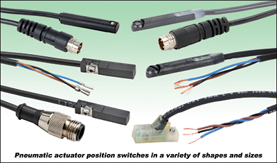
Pneumatic actuator position switches take many forms. They may fit into defined mounting locations or clamp onto the actuator exterior. Image courtesy of AutomationDIrect
Adding sensing elements creates a ripple effect of material and labor impacts. The switch parts must be selected to match the exact physical sensing need and the electrical characteristics of the intended control system. Designers must include the sensors on mechanical and electrical wiring diagrams. During installation, electricians must install the field wiring and ensure it is carefully routed to accommodate any motion. At startup, each actuator must be operated through its range, and technicians must adjust the position switches accordingly.
To take full advantage of the benefits offered by limit switches, engineers must define the operational and alarming characteristics in some type of sequence-of-operation document. Controls may be hardwired to accomplish this which, in turn, may require additional interlocks and indications. More commonly, a PLC and possibly an HMI will be used for this purpose, so these will need to be programmed.
After equipment is initially commissioned, the complete machine functionality must be thoroughly tested to exercise all possible operating conditions. This is performed to confirm basic operation and more-advanced timing conditions.
Actuator automation can significantly help operational and maintenance personnel down the road, especially if the system is configured with sufficient diagnostics to indicate the trouble. The flip side of this is that sensing elements introduce additional maintenance concerns — as they may fail or drift out of adjustment.
The bottom line is that pneumatic cylinder control and monitoring elements are a valuable addition but introduce certain costs which must be weighed against expected benefits.
Hybrid approach
To help contain costs, many designers pursue a hybrid approach to specifying actuator controls, especially when developing systems or subsystems that will be produced in quantity. When a piece of equipment is first undergoing development, engineers may tend to over-specify the instrumentation and put sensors in all possible locations.
While the system is in prototype mode, this allows them full access to use the automation platform for tracking cycle times and other operational parameters. This helps fine-tune operation, adjust timing and troubleshoot problems.
Once the machine is running as needed, however, designers can sharpen their pencils and evaluate exactly which position switches are required for operation and maintenance. During this value-engineering phase, unnecessary elements can be removed to lower costs while still providing the instrumentation needed for safe and reliable operation.
Pneumatic actuators are workhorses for many different types of machines. Whether manually controlled or operated as part of an automated system, there are many reasons to monitor actuator position and integrate this information into the control scheme. Careful attention to required physical and electrical characteristics will help designers choose the best fit for any application.
AutomationDirect
automationdirect.com
Filed Under: Pneumatic Tips