
Designers requiring linear motion should consider rodless cylinders to realize compact packaging and other benefits for pneumatic actuation, without the cost of electrically-driven options.
Contributed by Kevin Kakascik, Technical Marketing Engineer, AutomationDirect
Machine and equipment automation projects — whether performed by an original equipment manufacturer (OEM), a systems integrator (SI), or the capital projects group at a manufacturing facility — include many design phases. Requirements, costs, and benefits are typically assessed before the project is green-lighted and the conceptual design phase begins.
A detailed assessment of performance is defined during this phase as the team begins to specify products, technologies, and methods that will lead to successfully accomplishing the tasks at hand, within the constraints of budget and schedule. For many machines, there must be a way to perform and monitor linear motion with sufficient power, speed, and accuracy.
This article discusses some considerations for achieving reliable linear motion in a compact footprint, with an emphasis on rodless pneumatic cylinders.
Linear motion requirements and methods
Several basic parameters must be considered before selecting a linear motion solution:
- The load (and how much force is needed to move it)
- Overall travel (endpoints in each direction)
- Are intermediate stops or positioning needed?
- Speed of travel
- Accuracy
The two most popular motive technologies for linear motion are electric motors and pneumatic actuators. Each of these methods can be subdivided into a few categories:
- Electric (servo or stepper motors)
- Pneumatic (traditional or rodless cylinders)
Linear actions typically require a slide, often with guide rails, to support the mechanism with sufficient strength during operation and minimal friction. The choice for linear motion is how to drive this slide.
A servomotor, arranged as necessary with a gearbox and accompanying screw drive or rack-and-pinion, provides exceptional control of acceleration, velocity, deceleration, positioning, and accuracy to any location of travel. However, a servo solution is expensive and complex to procure, configure, and install. If the application demands such performance then a servo is the right solution, but many times it is overkill.
Stepper motors can be used instead of servomotors to save some money, while sacrificing a degree of precision and performance. They also are relatively expensive to configure and install but can deliver positioning anywhere through the range of linear travel.
A traditional pneumatic cylinder design would be a bargain compared to any electric motor drive option. Pneumatic cylinders are effectively tubes with a piston inside, connected to a rod that extends and retracts to provide the motive force as air pressure is introduced or exhausted from one side of the piston or the other. These designs are best for complete-stroke motion from one end of travel to another, although there are ways to control motion to stop mid-stroke.
A traditional cylinder can usually be direct-acting and does not require much else in the way of mechanical components. It might be packaged within the footprint of the linear travel, but often the pneumatic cylinder requires installation space at the end of the slide, usually somewhat greater than the amount of travel.
Besides being simple, basic pneumatic cylinders are inexpensive to install and maintain, and they provide an exceptionally large motive force compared to their size. Linear pneumatic motion can, therefore, be a cost-effective method suitable for many applications.
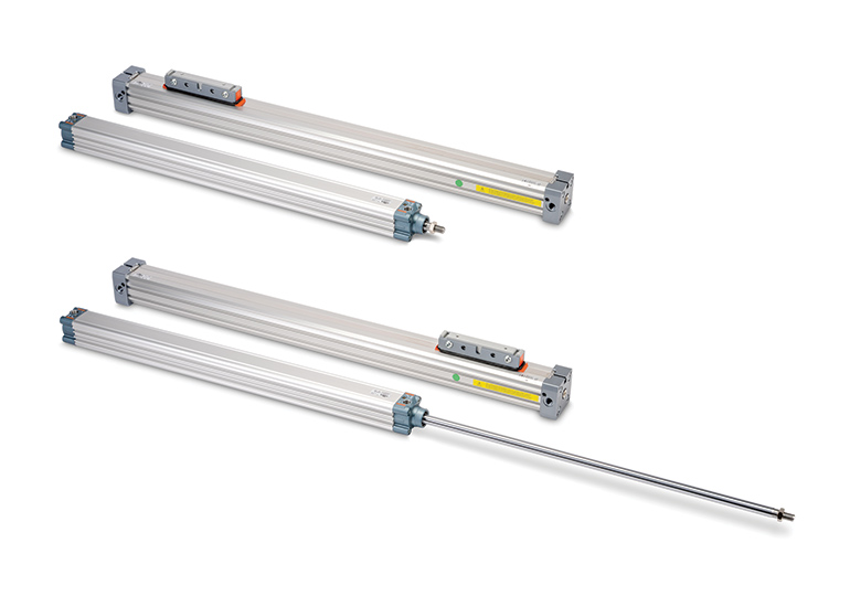
An alternate pneumatic option is called the rodless cylinder, which works in a similar way to a traditional, double-acting, rodded cylinder. The rodless cylinder tube also has an internal piston, often magnetized so its position can be detected by sensors, and there two air ports for introducing and exhausting air pressure on one side or the other.
However, the difference — as one might guess from the name — is that a rodless cylinder doesn’t have a rod connected to the piston. Instead, there is an external carriage that is connected to the piston, and it slides alongside the body of the cylinder, moving in tandem with the piston (Figure 1).
Rodless cylinders deliver many of the advantages of traditional rodded cylinders, but with the added benefit of allowing installation of the cylinder in tighter spaces. For linear motion, this type of packaging can be quite effective.
Keeping the design process in line
Consider a design team for a capital project at a large manufacturing facility. After one or two meetings, they review the linear motion needs. One team member is enamored by the high performance and additional capabilities of servo-driven linear motion. But after investigation, the team agrees to address the equipment linear motion needs with simple rodded pneumatic cylinders because this solution meets the need and compressed air is readily available. Having solved this problem by keeping things simple, they budget accordingly and move on to another topic.
Unfortunately, at a subsequent meeting, it is determined that the equipment will be located near a wall. This means that the motion stations planned for operation by pneumatic cylinders would end up with the cylinders extending beyond the machine footprint, which would interfere with the wall. Changing the concept back to electric motor driven actuators would technically solve the problem, but at this point would bust the budget.
Fortunately, a rodless pneumatic cylinder can solve both the technical and the commercial issues.
Solving a sticky situation
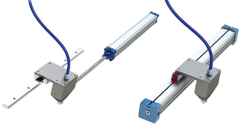
One example of where a rodless cylinder would be better suited than a traditional cylinder is on a glue station. For this station, a glue head needs to travel across a flat sheet of cardboard lying on a table, delivering a bead of glue as it moves.
In this case, a sheet of cardboard 500 mm wide (which means 500 mm of cylinder stroke is needed) is laid on a table, and a 480 mm long bead of glue is required. On one side of the table there is a guide fence ensuring the cardboard on the front side sits flush, while the machine has a space on the table on the backside of the fence that is 150 mm wide.
With a traditional cylinder, a model capable of 500 mm of stroke would have an overall retracted cylinder length of about 581 mm, or just under 23 in. long. This cylinder would need to be mounted next to and extending back past the fence. There would be a significant overhang outside the machine footprint, causing a problem since the cylinder body needs to be guarded so no one bumps into it. This overhang will also prevent installing the machine close to a wall, resulting in wasted working space (Figure 2).
For several reasons, a rodless cylinder is a better fit for this application than a rodded cylinder. A rodless cylinder with a similar operating rating as the rodded version will have end caps, which consume some space, approximately 150 mm on each end. But when installed above the machine table, the backside of the fence can accommodate this overhang, as can the front side of the table because it is open.
Another advantage of the rodless cylinder in this application is that it can support the glue head directly with no additional mechanism needed. If a rodded cylinder was used, the designer would need to account for the overhung load of the glue dispenser which would most likely require a mechanical linear slide to be incorporated, adding cost and complexity, and bringing the cost of the rodded cylinder solution close to the superior rodless option.
Linear motion knockout punch
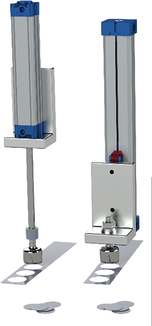
Rodless cylinders can save space in orientations other than horizontal, for example when used in vertical applications, such as a punch station.
This manufacturing facility is short on floor space but has a high-bay ceiling. As part of a redesign, a horizontal punch station is being updated to a vertical orientation to save floor space. The first and topmost station will punch a hole in a thin steel plate. When this station was on the ground it used a standard cylinder with a 200 mm stroke. The cylinder protruded up above the machinery by about 300 mm (Figure 3).
The vertical layout was proceeding perfectly until one problem was noticed. The punch cylinder would end up just 15 in. away from a fire sprinkler head deflector. Every other part of the machine is more than 6 in. below the top of the cylinder. Per NFPA 13 there must be a minimum of 18 in. clearance from a sprinkler head deflector, so this equipment stackup needed to be reduced by at least three inches. In this case, a complete redesign was avoided by switching to a rodless cylinder, saving the required six inches.
Rodless cylinders solve linear motion problems
Rodless cylinders are more expensive than rodded cylinders, and the space saving benefit becomes significant only for longer stroke lengths.
However, where space is at a premium for linear motion, especially for long stroke lengths, a rodless cylinder can often be used in place of a traditional rodded cylinder, especially if the mechanism will be attached to a carriage. In any case, the upfront and maintenance costs of a rodless cylinder will be far less than designs using motor-driven linear mechanisms.
AutomationDirect
automationdirect.com
Filed Under: Pneumatic Tips