
Far-reaching hydraulics powers a show-stopping display.
Contributed by Paolo Leutenegger, General Manager • Duplomatic Motion Solutions, Parabiago, Italy
Expo 2020, delayed by the Covid-19 pandemic, opens October 1 in Dubai. The world’s fair, set to welcome 190 participating countries with an estimated 25 million visitors from across the globe, aspires to increase awareness about the technology and environmental challenges humanity faces in the coming years.

The UAE Pavilion at Expo 2020 has 28 carbon and glass-fiber movable wings as long as 65 m and weighing up to 18 tons. All are actuated and controlled by a sophisticated hydraulic system. | courtesy of Santiago Calatrava LLC
The UAE Pavilion will be a major attraction at Expo 2020. The building, designed by Spanish architect Santiago Calatrava, is shaped like a falcon in flight — the official symbol of the UAE. The pavilion roof consists of 28 carbon and glass-fiber movable wings having masses ranging from 5 to 18 tons and total lengths from 30 to 65 m, all actuated and controlled by a sophisticated hydraulic system.
This unique project faced challenges well beyond those of typical industrial applications. A functional design was not enough, the final aim was to delight and astonish visitors. At the highest level, we had to provide a system that met client expectations in terms of outstanding performance and unrivalled aesthetics, all aligned with Expo 2020’s sustainability goals.
In practical terms, it means all wings must open and close in a synchronized harmonic fashion, absolutely silently, with smooth and stable motion, along with the highest reliability and power efficiency.
One major challenge is control of the wings. Some of them, due to their large size and weight, are actuated using two or three hydraulic cylinders that must be properly synchronized to avoid excessive stresses on the wing’s mechanical structure. Given the nature of the project, final validation of the control algorithms can be done only at the system level during commissioning. Therefore, particular care was devoted to the verification strategy, to identify and head off critical problems early on and reduce the overall risk.
Roof Wing Opening System
The hydraulic system for the Roof Wing Opening System (RWOS) is massive. It includes an approximately 1 MW hydraulic power unit (HPU), 2 km of piping, 46 hydraulic cylinders each weighing 1.5 tons, 46 valve stands to independently control each hydraulic actuator, and a complete automation and control subsystem that includes nine PLCs, dedicated software, 2,000 sensors and control points, and over 20 km of wiring harnesses.
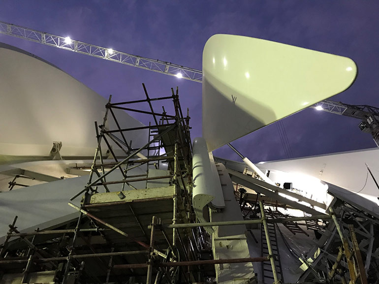
Despite working in an active construction site, Duplomatic engineers successfully finalized commissioning by tweaking control algorithms to ensure proper wing synchronization. | courtesy of Duplomatic Motion Solutions
The basic design idea is to control flow and system pressure independently to address every working condition. For this reason, fixed-displacement pumps controlled by inverter-driven electrical motors have been used. This allows an almost instantaneous setting of system pressure according to specific load requests.
Maximum oil flow rate is based on the time requirements specified for wing opening and closing sequences. It takes into consideration the kinematic characteristics and acceleration and deceleration profiles of every individual actuator.
System pressure must satisfy the dynamic load requirements for all actuators. That considers movements at given angular positions of each wing under worst-case load conditions due to the effects of gravity and wind-generated forces. (Relevant wind-load data have been derived from wind-tunnel testing of a scale-model pavilion, including all surrounding buildings, using an array of approximately 900 pressure sensors.)
To minimize power consumption, flow rate and system pressure are regulated according to the work cycle. For example, maximum pressure is needed at the start of opening movements, where flow demands are minimal. After acceleration, pressure decreases while flow rate increases. This trade-off between pressure and flow helps optimize power consumption.
Another essential requirement is silent operation. This led us to choose internal gear pumps which, among high-pressure pumps, have the lowest noise emission. Additionally, two pumps mount on each pump unit. The twin pumps are installed such that pulsation is in counter-phase, thus reducing pressure ripple on the pressure line and, consequently, noise generation. Likewise, the start-up sequence is designed to minimize the possibility of vibration.
System piping
System piping must take into account several different constraints. The main requirement is to guarantee high-pressure hydraulic fluid flow rates despite the sizeable distance and height between the HPU and actuators. Unpainted 316L stainless steel was selected as the piping material, considered the most reliable option to guarantee functionality with limited maintenance over the pavilion’s lifetime.
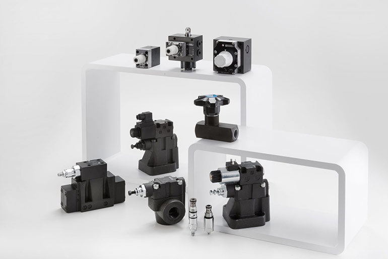
Duplomatic supplied all the valves, cylinders and pumps, and the proportional flow control valves were specifically designed and manufactured for the Expo 2020 project. The company’s engineers also developed the motion control cards and motion algorithms. Siemens provided the asynchronous electric motors, inverters, PLCs and Profinet network. | courtesy of Duplomatic Motion Solutions
The HPU provides more than 2,000 lpm flow rate at a constant 210 bar working pressure. The HPU is located in the basement, 5 m below ground level, 45 m from the point where pipes reach the roof and approximately 100 m from the most-distant wing actuator. To minimize pressure losses and withstand design and test pressure 1.5 times the working pressure, engineers selected a 5 in. size main pipe for the high-pressure line to the roof and an 8 in. size low-pressure pipe for return flow.
The riser, the vertical section of pipes reaching the roof, is 15 m long. This represents a real challenge considering that the high-pressure line weighs about 50 kg/m for bare steel without fluid inside. Special supports are each designed to carry more than a half metric ton. The supports must also compensate for structural movements of the building, such as for extreme temperature swings typical in the desert climate. Another concern is that the steel roof and concrete building expand and contract at different rates, due to thermal changes. Thus, flexible hoses connect the riser to the roof piping.
On the roof, the two pipes form loops, called ring pipes, which ensure fluid distribution to each wing. The ring topology lets fluid take the easiest path to the actuators. Each ring is composed of numerous curved sections connected by flanges, forming a segmented loop that allows deformation induced by thermal loads. Pressure lines range between 4 and 3 in. in diameter, and 6 to 4 in. for the return lines. Overall length of each loop is approximately 550 m for the pressure line and 590 m for the return.
Smaller lines, called wing pipes, branch off the ring pipes and supply the actuators. They are sized according to flow requirements and run along the steel wing ribs to the valve manifolds. Flexible hoses between ring and wing pipes allow independent movement with respect to each other.
Particular attention was devoted to the pipe supports. The pipe network must expand as oil temperature rises and allow for roof movements due to thermal effects and wind loads. Special supports let the pipes slide and accommodate any deformation. In essence, the entire pipe ring “floats” on these supports.
Finally, because the roof steel structure could amplify system vibrations and generate noise inside the pavilion, elastic elements were added at connection points between the hydraulic system and supports.
Actuators and motion control
The motion control system follows Duplomatic’s standard philosophy in controlling the speed of a hydraulic axis by piloting a compensated proportional flow valve and using a position-transducer signal as feedback.

The hydraulic system controlling the Roof Wing Opening System includes a 1 MW hydraulic power unit, 2 km of piping and 46 hydraulic cylinders. | courtesy of Santiago Calatrava LLC
Movement of each hydraulic actuator is independently controlled by one dedicated proportional control valve. Additional valves manage lock-in position, emergency closing and direction of movement. Valves mount on a block located on the back of each actuator, a compact design that ensures fast response. For safety, relief and lock valves are installed directly on the cylinder.
Each axis has a dedicated motion control card (CAC) and, in multi-axis wings, an additional control card acts as synchronism supervisor (SSC). All cards communicate internally via a dedicated CAN bus and connect to the automation and control subsystem through a PROFINET interface.
Wing control electronics manages the valves, as well as pressure and stroke transducers and temperature sensors, and executes commands to operate the wing. The angular speed profile in terms of travel distance and acceleration and deceleration times is defined according to hydraulic circuit characteristics and power management requirements. Standard full-stroke opening/closing movements are performed in 180 ±2 sec. Fast closing in 120 sec is permitted in critical weather conditions.
Due to the project’s unusual characteristics and the difficulty in predicting dynamic behavior of each wing, a special open-loop algorithm was implemented for controlling the angular speed of a wing based on cylinder stroke feedback. Kinematic parameters of each actuator depend on the wing geometry and position. Consequently, each cylinder has a unique set that is stored in the firmware.
The system calculates output to the proportional flow valve based on the actual position and angular profile. Due to the open-loop control, tracking quality of the kinematic profile is strictly linked to the behavior of the specially designed proportional flow valve. To compensate for deviations induced by external influences and tolerances in mechanical and hydraulic components, a Speed Adaptive Control (SAC) algorithm looks at a number of checkpoints as a supervisor and forces speed corrections at each checkpoint. This minimizes the cumulated positioning error in the remaining part of the stroke.
Synchronism control, managed by the SSC, is required for wings with two or three axes. A closed-loop PI control based on a Master-Slave concept is implemented in the motion controllers, using synchronization set points from the SSC. It’s active only for slave axes. The aim is to minimize synchronism error under the maximum acceptable limit of ±10 mm.
The main advantage with this concept is that disturbances and oscillations on a slave axis do not influence the entire controller. The Master is controlled in open-loop avoiding the complexity arising from the system’s low natural frequency, and it makes tuning of the synchro controller independent from the wing control. SSC, being the fastest observer, also immediately stops wing movement if synchronization error exceeds an acceptable threshold limit.
A central Building Management System networked to the main PLC commands roof opening and closing. The control and automation subsystem manages the RWOS. Ten wing automation cabinets located on the roof house remote PLCs and electronics for actuator control and synchronization. Parametrization of any device can be performed remotely. Thus, no direct roof access is required, simplifying maintenance. Three UPS subsystems, which supply the main PLC and all control subsystems, allow 10 minutes of operation to secure the RWOS in case of main power loss.
System verification and testing
The main verification challenge relates to the system’s size and to the difficulty of performing representative tests before final commissioning on site. The aim was to identify risks during the development phase, combining system modelling, simulations and tests at the subsystem level.
System modeling and simulations analyzed two critical aspects: System pressure losses throughout the entire operating sequence and the actuators’ power demands during movements. They answer to the basic question: Can the cylinders move under any possible load condition? Analysis also determines pressure reserve available under worst-case operating conditions.
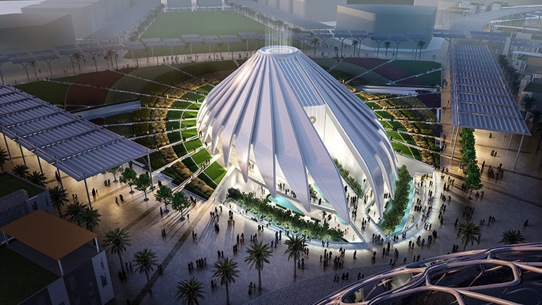
The UAE Pavilion, designed by Spanish architect Santiago Calatrava, is shaped like a falcon in flight — the official symbol of the UAE.
Design data include the pipe system model; pipe elements that consider hydraulic capacity, inductance and losses; cylinder flow and physical behavior; as well as different temperatures and oil types. Results showed the need to modify system pressure at the beginning of the opening cycle, to overcome high loads, and during the closing process where some pressures were insufficient. Increasing system pressure from 140 to 160 bar resulted in ample design margin during all operating conditions.
Hardware-in-the-Loop simulation is a common technique for system-level testing of embedded systems. Here, the control hardware links to a virtual environment that includes the cylinder subsystem. The HiL test bench simulates virtual movements of the wings, which are controlled by the motion control cards (CAC and SAC) and the corresponding hydraulic valves.
The main objective was to test the motion control algorithms to ensure performance specifications are met and all software bugs identified. HiL simulations show that the Speed Adaptive Control algorithm holds position error within specified limits during both opening and closing, for all wings, under worst-case load conditions, and opening/closing time requirements are met. Complying with time tolerances is a precondition to ensure the synchronous movement of all wings on the roof. Likewise, the SSC controller for multi-axis wings meets angular-deviation tolerances during all test cases. This guarantees low bending moments and damage-free wing movements.
The wing test bench is a versatile hardware replica of a wing subsystem, built at DMS. Although downscaled to limit space and energy consumption, it accurately replicates the properties of both single-and multi-axis wings. It includes three hydraulic cylinders (stroke 1,000 mm, bore 50 mm, rod 28 mm) including SSI linear transducers, related control-axes boards and valve blocks; a hydraulic power unit running at 120 bar and constant flow; a PLC acting as the wing controller; and ancillary sensors, remote I/O modules and HMI.
The main objectives were to validate firmware in the motion control boards; and debug and validate the automation software. To thoroughly test the robustness of the motion algorithms, the hydraulic circuit was equipped with additional proportional pressure valves that inject external disturbances to simulate wind loads.
Results confirmed that external forces do not affect the overall opening time. In Master-Slave controlled mode, the synchronism control loop acting on each slave is unaffected by the other slave axes. This demonstrates that the synchronization algorithm holds synchronization error on the slave axes to well below the acceptable threshold of ±10 mm.
Commissioning on site
Simulations, HiL and test bench results confirm the feasibility and reliability of Duplomatic’s technical solution. However, some simplifications in the model and behaviors not fully validated in the simulations required additional analysis of the real system on site.
Once equipment was installed, several tuning activities had to be performed. On the HPU, particular care had to be devoted to determine the correct delays for switching the valves in order to avoid abrupt pressure build-ups/losses and vibrations or noise.
The kinematic parameters of each hydraulic actuator had to be verified due to differences between the design data and actual construction of the wing structures. In the majority of cases, the original parameters were almost identical to the measured ones. However, on some of the longer wings, major discrepancies were identified with the manufacturing tolerances, which had to be corrected to prevent out-of-synchronization errors.
The procedure we identified to overcome this hurdle was meticulous and time-consuming: Each problem wing was actuated separately using a modified version of the software where synchronization between master and slave cylinders was deactivated. The wing moved only with the master cylinder, while slave cylinders followed movements that prevent wing deflections. The relationship between the cylinders as wing angle changes was recorded through temporary sensors and cylinder stroke transducers. This allowed us to verify the revised kinematic profile, including calculations of each parameter used within the axis control cards.
The other major difficulty involved the coordination of activities on the roof among many different subcontractors. Any delay in one activity impacted the work of all the other companies, which made planning almost impossible and required a redefinition of priorities on a daily basis.
Moreover, the difficulty in accessing areas of the roof, due to the complexity of the steelwork and slope of the roof — in some areas on the order of 45° — and the large number of workers led to uncontrolled walkways and regular damage to the equipment installed.
The most important milestone was achieved in December 2020, where all 28 wings on the roof were moved perfectly synchronously for the first time, confirming system behavior in full accordance with simulations and laboratory testing activities. Installation is now complete. Presently, commissioning activities involve the final alignment of wings with respect to the stationary roof structure, to ensure the best aesthetic effect.
Duplomatic Motion Solutions
duplomatic.com
Filed Under: Cylinders & Actuators, Trending, Valves & Manifolds