
O-rings from Parker Hannifin’s Seal Group
O-rings are probably the most common fluid power seals. They’re made by the billions by manufacturers all around the world, and they prevent leaks in everything from pumps and valves to cylinders and connectors. The compact, economical components handle both static and dynamic operations, in pneumatic and hydraulic applications.
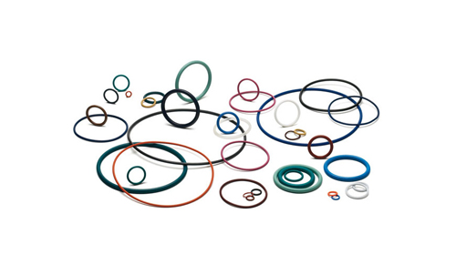
These simple seals consist of a donut-shaped ring (technically, a toroid) with a circular cross section. They’re typically made of elastomers like Buna N, Neoprene or silicone, but they also come in plastics like PTFE, metals and other materials. Sizes range from fractions of an inch in diameter to several meters across.
O-rings seal by mechanical deformation that creates a barrier to a fluid’s potential leak path between two closely mated surfaces. O-rings are typically installed in a groove that’s machined or molded in one of the surfaces to be sealed. Their rubber-like properties let the devices compensate for dimensional variations in the mating parts.
When properly sized, the clearance between the surfaces is less the OD of the O-ring. Thus, as the two surfaces contact, forming a gland, they compress the O-ring, which deforms the round cross section. This diametrically squeezes the seal, and the resulting force ensures surface contact with the inner and outer walls of the gland.
With little or no pressure, the natural resiliency of the elastomer compound provides the seal and keeps fluid from passing by. Increasing the squeeze (say, by using a larger diameter O-ring in the same-size groove) increases deformation and sealing force. But that can lead to problems in higher-pressure dynamic applications.
Applying fluid pressure pushes the O-ring against the groove wall on the low-pressure side, increasing the sealing force. Interference between the seal and mating surfaces lets the O-ring continue to operate leak-free. At higher pressures, the O-ring deforms to a somewhat “D” shape, and contact area between elastomer and gland surfaces may double from initial zero-pressure conditions. Due to the elastomer’s resiliency, releasing pressure lets the O-ring return its original shape, ready for the next pressure cycle. It also lets properly designed O-rings seal in both directions.
Extreme pressures, however, can force elastomer material into the small clearance between the mating surfaces just beyond the groove. Ultimately, the O-ring material shears and flows into the so-called extrusion gap, and the seal fails. Dynamic applications can hasten seal extrusion. But even in static applications, high pressure can stretch assembly bolts and open the extrusion gap sufficiently to permit leakage.
While O-rings are relatively straightforward seals, there are still a number of design considerations when specifying them. For starters, they come in a wide range of materials and countless compounds and variations. Matching the material to the application, however, lets them provide excellent fluid compatibility, withstand various operating environments and handle temperature extremes. Other considerations include static versus dynamic (rotary or axial) conditions, operating pressure, and whether the system sees pressure spikes. These, in turn, let engineers specify design parameters like proper gland dimensions, gland surface finishes, seal cross-section diameter, material hardness, initial compression, clearance gaps, and even how much the seal expands or contracts in relation to its mating surfaces as temperatures change. Properly designed, O-rings provide long, trouble-free life in countless applications.
Filed Under: Sealing