Contributed by Frances Richards
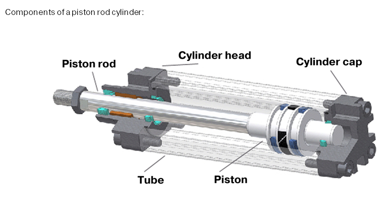
Pneumatic cylinders, also called air cylinders, pneumatic actuators, or pneumatic drives, are relatively simple mechanical devices that use the energy of compressed air and turn it into linear motion. Lightweight and low maintenance, pneumatic cylinders generally operate at lower speeds and less force than their hydraulic or electric counterparts, but are a clean and cost-effective option for reliable linear motion in many industrial environments. The most common design consists of a cylinder or tube that is sealed on both ends, with a cap at one end and head at the other end. The cylinder contains a piston, which is attached to a rod. The rod moves in and out of one end of the tube, actuated by compressed air. Two main styles exist: single-acting and double-acting.

Image courtesy of Hafner Pneumatik
In single-acting pneumatic cylinders, air is supplied through one port to one side of the piston, causing the piston rod to extend in one direction for a task such as lifting an object. The other side vents air to the environment. Movement in the opposite direction occurs most often by means of a mechanical spring, which returns the piston rod to its original or base position. Some single-acting cylinders use gravity, a weight, mechanical motion, or an externally mounted spring to power the return stroke, although these designs are less common. In contrast, double-acting pneumatic cylinders feature two ports that supply compressed air to both extend and retract the piston rod. Double-acting designs are far more typical throughout industry, with an estimated 95% of applications using this cylinder style. However, in certain applications, a single-acting cylinder is the most cost-effective and appropriate solution.
In a single-acting cylinder, the design can be “base position minus” with spring return, or “base position plus” with spring extend. This depends on whether the compressed air is used to power the out-stroke or the in-stroke. Another way to think about these two options is push and pull. In the push design, air pressure creates a thrust, which pushes the piston. With the pull design, air pressure produces a thrust that pulls the piston. The most widely specified type is pressure-extended, which uses an internal spring to return the piston to its base position when the air exhausts. One advantage of the single-acting design is that in case of either power or pressure loss, the piston automatically returns to its base position. A disadvantage of this style is the somewhat inconsistent output force during a full stroke due to the opposing spring force. Stroke length is also limited by the space the compressed spring requires, as well as available spring lengths.

For position detection, a magnet can be installed on the cylinder piston. Sensors mounted on the cylinder body can then gather information from the magnet and determine piston position. Hall effect sensors and reed switches are often used for this purpose. Another cylinder component to consider involves cushioning. As compressed air enters the cylinder, the piston will move rather quickly and potentially cause a hard impact against the head or end cap. To avoid stressing cylinder components and transmitting vibration to the rest of the machine, cushioning can be used at the ends of the cylinder. For smaller cylinders, which many single-acting cylinders tend to be, flexible shock absorbers made of polyurethane elastomers are often used. These bumpers are installed on the head and end caps or integrated into the piston itself.
With regard to sizing, it’s important to remember that the cylinder diameter is directly proportional to the amount of force it can generate from the input air pressure. The following formula is useful:
F = (P x A) – f
F is the cylinder’s force (N); P is air pressure (MPa); A is piston area (mm2); and f is friction drag (N).
Also keep in mind that with single-acting cylinders, some work is lost due to the opposing spring force. This force reduction must be taken into account when sizing this cylinder type. Diameter and stroke are the most important factors to consider during sizing calculations. Diameter refers to piston diameter, which defines its force relative to the air pressure. Available cylinder diameters are defined by the cylinder type and ISO or other standards. Stroke defines how many millimeters the piston and piston rod can travel. A general rule is that the larger the cylinder bore is, the greater force output. Typical cylinder bore sizes range 8 to 320 mm.
A final consideration is mounting style. Depending on the manufacturer, many configurations are available. Some of the most common include foot mount, tail mount, rear pivot mount, and trunnion mount. The best option will be determined by the specific application and other system components.
Filed Under: Cylinders & Actuators, Fluid Power Basics, Pneumatic Tips
